


Gas Pressure Regulators Selection Guide
Gas Pressure Regulators Selection Guide
I. Core Working Principle: Pressure Regulation and Stabilization
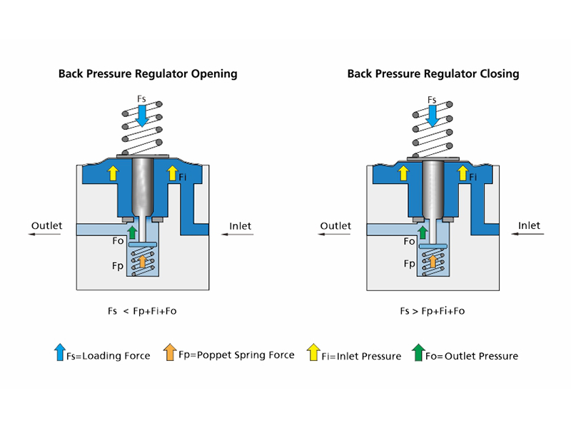
The core functions of an industrial gas pressure regulator are pressure reduction and stabilization. Its working principle is mainly based on the force balance principle: a sensing element (e.g., diaphragm or piston) detects changes in outlet pressure and automatically adjusts the valve orifice opening to offset the impacts of inlet pressure fluctuations and flow variations, thereby maintaining a stable outlet pressure.
A typical pressure regulator consists of three basic functional units:
Pressure Sensing Unit: Usually composed of a precision elastic diaphragm or a piston. One side is exposed to the regulator’s outlet pressure (i.e., working pressure) and can sensitively detect minor changes in outlet pressure.
Pressure Regulating Unit: Mainly made up of a seat and a poppet. The gas flow of high-pressure gas is controlled by adjusting the opening between the poppet and the seat to achieve pressure reduction.
Control Unit: Includes an adjustment spring and a handwheel. The user compresses the adjustment spring by turning the handwheel, and the downward force generated determines the set outlet pressure value.
Working Process
Initial State: Rotate the adjustment handwheel counterclockwise to fully release it; the adjustment spring is in a relaxed state and exerts no force on the diaphragm. At this time, the poppet is tightly pressed against the seat by the return spring or gas pressure, and the valve is closed.
Pressure Setting: Rotate the adjustment handwheel clockwise to compress the adjustment spring, which applies a downward force (F_spring) to the diaphragm. This force pushes the diaphragm, along with the connected valve stem and poppet, downward to overcome the force of the poppet return spring and open the valve orifice. High-pressure gas flows through the narrow valve orifice for throttling and pressure reduction, then into the outlet chamber, and the outlet pressure (P_out) rises gradually.
Force Balance State: The rising outlet pressure acts on the lower side of the diaphragm, generating an upward force (F_pressure). When F_pressure balances with F_spring, the diaphragm stops moving and the poppet stabilizes at a specific opening. The outlet pressure is then maintained at the user-set value.
Automatic Pressure Stabilization Process
When outlet pressure rises (e.g., downstream gas equipment is shut down): P_out increases instantaneously, causing F_pressure > F_spring. The diaphragm is pushed upward, driving the poppet to move up, reducing or even closing the valve orifice and decreasing gas flow, thus bringing P_out back to the set value.
When outlet pressure drops (e.g., downstream gas consumption increases): P_out decreases instantaneously, causing F_pressure < F_spring. The spring force pushes the diaphragm and poppet downward, increasing the valve orifice opening and gas flow, thus raising P_out back to the set value.
When inlet pressure fluctuates (e.g., cylinder pressure gradually drops during use): A drop in inlet pressure (P_in) temporarily causes a downward trend in outlet pressure, breaking the force balance. The stabilization process is the same as above, and the poppet will automatically open wider to maintain stable outlet pressure.
II. Main Types and Characteristics
Industrial gas pressure regulators are classified into the following categories based on different application requirements and structural features:
By Action Mode
Direct-Acting Type: High-pressure gas flows in from below the valve disc and tends to open the valve. It usually needs to be matched with a reverse-acting sensing element and is now rarely used.
Reverse-Acting Type: The most mainstream type. High-pressure gas flows in from above the valve disc and tends to close the valve. Its advantages include better sealing performance (the higher the outlet pressure, the tighter the valve orifice closes), lower spring force required for the same set pressure, and more precise control.
By Structural Form
Diaphragm Type: Adopts rubber or metal diaphragms as pressure sensing elements. It features high sensitivity and fast response speed, making it suitable for high-purity and corrosive gases—because the diaphragm isolates the flow channel from components such as springs to prevent contamination. However, the pressure-bearing capacity of the diaphragm is relatively low.
Piston Type: Uses metal pistons as pressure sensing elements. It has a robust structure, high pressure-bearing capacity and good durability, suitable for high-pressure and large-flow working conditions (e.g., pressure reduction of nitrogen and air pipelines). Its sensitivity is slightly lower than the diaphragm type, and it is sensitive to particulates in the gas, which may require a filter.
By Stage Number
Single-Stage Regulator: Simple in structure and cost-effective. However, its pressure stabilization accuracy is greatly affected by inlet pressure changes (called droop characteristic)—i.e., the outlet pressure will drop to a certain extent as the cylinder pressure decreases from full to empty. It is suitable for occasions with low requirements for pressure stability.
Two-Stage Regulator: Internally integrates two series-connected single-stage regulators. The first stage pre-reduces the drastically fluctuating high inlet pressure to an intermediate pressure, and the second stage performs fine adjustment to output an extremely stable pressure. Its outlet pressure is almost unaffected by changes in inlet pressure and flow. It is ideal for high-precision applications such as laboratory analytical instruments, laser cutting and welding. Of course, it has a higher cost and complexity.
III. Key Performance Parameters and Selection Guide
Correct selection is a prerequisite for the safe and efficient operation of pressure regulators. The main factors to consider are as follows:
Gas Medium
This is the primary factor! A pressure regulator dedicated to the specific gas must be selected.
Flammable gases (e.g., hydrogen, acetylene, propane): The outlet connector must use left-hand threads (reverse threads) to prevent misconnection to oxidizing gas pipelines. The valve body is usually made of copper alloy, but regulators for acetylene must contain no copper or silver (<70%) to avoid the formation of explosive copper acetylide.
Oxidizing gases (e.g., oxygen, nitrous oxide): All components must undergo strict degreasing and cleaning, with absolute oil prohibition. Even a trace of oil in contact with high-pressure oxygen can cause violent combustion or even explosion. The valve body is typically made of brass or stainless steel.
Corrosive/high-purity gases (e.g., chlorine, hydrogen sulfide, electronic-grade special gases): A diaphragm-type stainless steel regulator (e.g., 316L SS) must be selected. All gas-contacting components have excellent corrosion resistance and undergo high-grade surface treatment (EP polishing) and strict cleaning to ensure gas purity.
Pressure Parameters
Maximum Inlet Pressure: Should be greater than or equal to the maximum pressure of the cylinder or pipeline.
Outlet Pressure Range: Its maximum and minimum values must cover the pressure required for the process.
Rated Outlet Pressure: The maximum safe pressure the regulator can withstand when the outlet end is accidentally closed.
Flow Capacity
Select according to the maximum gas consumption of downstream equipment, usually expressed by Cv value (flow coefficient) or Nm³/h. The flow capacity of the selected regulator must meet the maximum demand with a certain margin, but it should not be excessively large—otherwise, the regulation performance will deteriorate at low flow rates.
Connection Method
The interface size and thread standard (e.g., NPT, G, M) with the cylinder and downstream pipeline must match.
Material
The materials of the valve body, diaphragm and seals must be compatible with the gas. Common material combinations are:
General industrial gases (air, nitrogen, argon): Brass valve body + NBR seals.
Corrosive/high-purity gases: 316L stainless steel valve body + PTFE/EPDM seals.
Oxygen: Brass or stainless steel valve body + oil-free treatment + PTFE/Nylon seals.
IV. Safe Operation and Maintenance
Before Installation: Inspect the regulator for damage and confirm that the marked gas type is consistent with the cylinder.
When Opening: Always open the cylinder main valve slowly to avoid damage or safety accidents caused by the instantaneous impact of high-speed gas flow on internal components of the regulator.
Routine Inspection: Regularly check all interfaces for leaks with leak detection fluid.
Maintenance: Pressure regulators are precision equipment. In case of pressure instability, leakage or failure to adjust pressure, they must be repaired or replaced by professional personnel. Unauthorized disassembly is strictly prohibited.
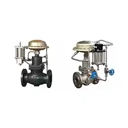 Difference Between Pilot Operated and Direct-Acting Self-operated Control Valve
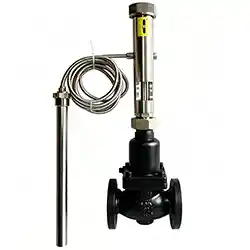 Classification of Self-Operated Control Valves
 What is a Plug Valve?
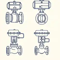 How to Choose Between Electric Valves and Pneumatic Valves?