


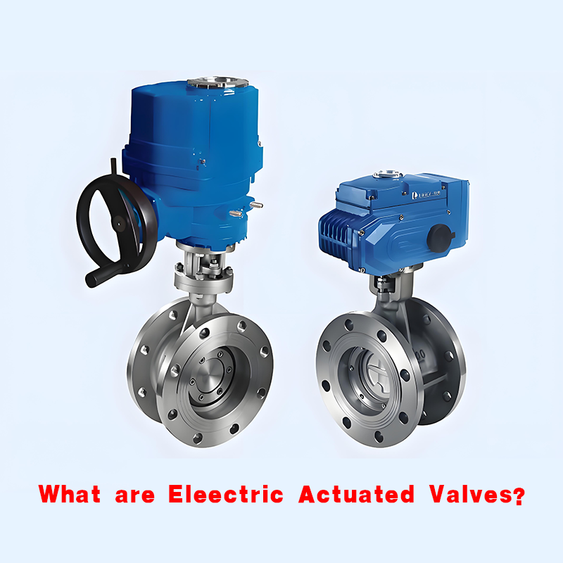
What Are Electric Actuated Valves?
Electric Valves: Core Knowledge Collection
Working Principle of Electric Valves
The operating torque of electric valves is larger than that of ordinary valves. The opening and closing speed of electric valves can be adjusted. They have a simple structure and are easy to maintain. They can be used to control the flow of various types of fluids such as air, water, steam, various corrosive media, sludge, oil products, liquid metals, and radioactive media. In contrast, due to the buffering characteristics of gas itself during the operation of traditional pneumatic valves, they are not easy to be damaged due to jamming, but they must have an air source, and their control system is more complex than that of electric valves. Valves of this type should generally be installed horizontally in pipelines.
Simply put, an electric valve uses an electric actuator to control the valve, thereby realizing the opening and closing of the valve. It can be divided into two parts: the upper part is the electric actuator, and the lower part is the valve. It is advisable to carry out simulated action and pressure test on the electric valve before installation.
Advantages
Good effect on liquid media and large-diameter gas; not affected by climate; not affected by the pressure of compressed air.
Disadvantages
High cost; poor performance in humid environments.
Operating Principle and Applications
An electric valve is usually composed of an electric actuator and a valve. The electric valve uses electrical energy as power to drive the valve through the electric actuator to realize the opening and closing action of the valve, thereby achieving the purpose of opening and closing the pipeline medium.
A solenoid valve is a type of electric valve; it uses the magnetic field generated by the electromagnetic coil to pull the valve core, thereby changing the on-off state of the valve body. When the coil is de-energized, the valve core returns to its original position by the pressure of the spring.
Electric valve: Used for analog quantity regulation of fluid flow in liquid, gas and air system pipelines, which is AO control. It can also be used for two-position on-off control in the control of large valves and air systems.
Operation Methods
1 Preparation Before Operation
1.1 Before operating the valve, carefully read the operation instructions.
1.2 Before operation, it is necessary to clearly know the flow direction of the gas and check the valve opening and closing marks.
1.3 Check the appearance of the electric valve to see if it is damp. If it is damp, dry it; if other problems are found, handle them in time, and do not operate with faults.
1.4 For electric devices that have been out of service for more than 3 months, check the clutch before starting. After confirming that the handle is in the manual position, check the insulation, steering and electrical lines of the motor.
2 Notes for Electric Valve Operation
2.1 When starting, confirm that the clutch handle is in the corresponding position.
2.2 If the electric valve is controlled in the control room, set the transfer switch to the REMOTE position, and then control the opening and closing of the electric valve through the system.
2.3 If it is manually controlled, set the transfer switch to the LOCAL position, and operate the opening and closing of the electric valve on site. The electric valve will automatically stop working when it is fully opened or closed, and then set the operation transfer switch to the middle position.
2.4 When operating the valve on site, monitor the valve opening and closing indicators and the operation of the valve stem, and ensure that the valve opening and closing degree meets the requirements.
2.5 When fully closing the valve by on-site operation, stop the electric valve closing before the valve is fully closed, and use inching to fully close the valve.
2.6 For valves with adjusted stroke and over-torque controllers, when fully opening or closing the valve, monitor the stroke control. If the valve does not stop when it reaches the position, immediately stop the machine manually in an emergency.
2.7 During the process of opening and closing the valve, if the signal indicator light shows an error or the valve makes an abnormal noise, stop the machine for inspection in time.
2.8 Turn off the power supply of the electric valve after successful operation.
2.9 When operating multiple valves at the same time, pay attention to the operation sequence and meet the production process requirements.
2.10 When opening a large-diameter valve with a bypass valve, if the pressure difference between the two ends is large, first open the bypass valve to adjust the pressure, then open the main valve; after the main valve is opened, close the bypass valve immediately.
2.11 When receiving and sending pigging balls (devices), the ball valves they pass through must be fully opened.
2.12 Ball valves, gate valves, globe valves and butterfly valves can only be fully opened or closed, and are strictly prohibited from being used for regulation.
2.13 During the operation of gate valves, globe valves and flat gate valves, when closing or opening to the top dead center or bottom dead center, turn back 1/2 to 1 turn.
Maintenance
Daily Maintenance of Electric Valves
1. Electric valves should be stored in a dry and ventilated room, and both ends of the passage must be blocked.
2. Electric valves stored for a long time should be inspected regularly, dirt should be removed, and anti-rust oil should be applied on the processed surfaces.
3. After installation, regular inspections should be carried out, including the following main items:
(1) Wear condition of the sealing surface.
(2) Wear condition of the trapezoidal thread of the valve stem and valve stem nut.
(3) Whether the packing is outdated and invalid; if damaged, it should be replaced in time.
(4) After maintenance and assembly of the electric valve, a sealing performance test should be carried out.
For electric valves in operation, all valve parts should be complete and intact. Bolts on flanges, threads and brackets must not be missing, threads should be intact, and loosening is not allowed. If the fastening nut on the handwheel is found loose, it should be tightened in time to avoid wear of the connection or loss of the handwheel and nameplate. If the handwheel is lost, it is not allowed to replace it with an adjustable wrench, and it should be replenished in time. The packing gland is not allowed to be skewed or have no pre-tightening gap. For electric valves in environments that are easily contaminated by dirt such as rain, snow, dust and sand, a protective cover should be installed on the valve stem. The scale on the electric valve should be kept complete, accurate and clear. The lead seal, cap, pneumatic accessories, etc. on the electric valve should be complete and intact. The thermal insulation jacket should have no depressions or cracks.
It is not allowed to strike, stand on or support heavy objects on the electric valve in operation; especially non-metallic electric valves and cast iron electric valves, which are strictly prohibited.
Classification
1. Valves for Oil and Gas Wellhead Equipment
Valves for oil and gas wellhead equipment are mainly forged steel parallel gate valves (single or double gate, with or without diversion holes), mud valves, angle throttle valves, special parallel control valves for oilfields, special straight-through check valves for oilfields, special parallel gate valves for water injection/polymer injection, clamp-type parallel gate valves, pilot-operated safety valves and check valves that meet the American API6A standard.
The nominal pressure levels of electric valves for oil and gas wellhead equipment are API2000psi, 3000psi, 5000psi, 10000psi, 15000psi, 20000psi; nominal diameters are DN46~228mm (113/16in~9in); temperature grades are K (-60~182℃), L (-42~182℃), P (-29~182℃), R (room temperature), S (-18~166℃), T (-18~196℃), U (-18~121℃), V (2~121℃); material requirements are AA, BB, CC, DD, EE, FF, HH; material performance requirements are according to 36K, 45K, 60K, 75K; product technical requirements are according to PSL1 (Product Specification Level 1), PSL2 (Product Specification Level 2), PSL3 (Product Specification Level 3), PSL4 (Product Specification Level 4).
2. Valves for Oil and Gas Long-Distance Pipelines
Valves for oil and gas long-distance pipelines are mainly flat gate valves (single or double gate, with or without diversion holes) that meet the American API6D standard; forged steel or cast steel three-piece, top-entry or fully welded fixed ball valves; oil-sealed or pressure-balanced plug valves; swing or butterfly check valves, pigging check valves; pigging valves, etc.
The nominal pressure levels of these electric valves are CL150 (PN2.0MPa), CL300 (PN5.0MPa), CL400 (PN6.4MPa), CL600 (PN10.0MPa), CL900 (PN15.0MPa), CL1500 (PN25.0MPa), CL2500 (PN42.0MPa); nominal diameters are DN50~1500mm (2in~60in); fire resistance test technical requirements are according to ISO10497; pressure test of electric valves is according to ISO5208.
3. Valves for Nuclear Power
Electric valves for nuclear power have higher technical characteristics and requirements than those for conventional large thermal power stations. Common valve types include gate valves, globe valves, check valves, butterfly valves, safety valves, main steam isolation valves, ball valves, diaphragm valves, pressure reducing valves and control valves, etc.; the highest technical parameters of representative electric valves are: large diameter DN1200mm (nuclear class 3 butterfly valve), DN800mm (nuclear class 2 main steam isolation valve), DN350mm (nuclear class 1 primary circuit gate valve); maximum pressure: about 1500 pounds; maximum temperature: about 350℃; medium: coolant (borated water), etc. The production requirements for nuclear-grade electric valve products are usually in accordance with nuclear industry standard EJ, American ASME, IEEE standards and French PWR nuclear island mechanical equipment design and construction rules RCC-M, etc.
The specific types and parameters of electric valves for nuclear power development are as follows:
(1) Gate valves with stuffing boxes:
a Hydraulically driven gate valves. This valve uses its own pressure water to push the piston to open or close. The nominal diameter of the valve: DN350, 400mm; working pressure: PN17.5MPa; working temperature: 315℃. b Fully enclosed electric gate valves. This valve should adopt a special screen-closed motor, and the gate plate is opened and closed through an internal planetary reduction mechanism working in water. The nominal diameter of the valve: DN100~800mm; working pressure: PN2.5~45.0MPa; working temperature: 200~500℃.
Note: Advantages of the above two gate valves without stuffing boxes: no packing seal, avoiding external leakage points, and reducing energy consumption at the same time. Disadvantages: complex structure and high cost.
(2) Globe valves for nuclear power:
Globe valves used in auxiliary pipelines. This valve usually has three structures, namely packed globe valves, bellows globe valves and metal diaphragm globe valves. The medium of the valve is water and steam with medium parameters (medium temperature and medium pressure); nominal diameter: DN10~150mm.
(3) Butterfly valves for nuclear power:
Butterfly valves used in cooling systems and systems transporting air medium in containment. This valve usually has three structures, namely coaxial direct-connected rubber-lined butterfly valves, eccentric metal-sealed butterfly valves and double-acting (the butterfly plate disengages from the sealing surface before rotating) metal-sealed butterfly valves. The nominal diameter of the valve: DN≤2500mm; working pressure: PN<4.0MPa; working temperature: 100~150℃. In addition, quick-closing butterfly valves used in air duct systems with nominal diameters of DN400~1200mm are also listed as the development direction.
(4) Pilot-operated safety valves with detectors for nuclear power:
Pilot-operated safety valves with detectors used in nuclear island systems. The use of pilot-operated safety valves with detectors can change the principle of the two contacts for controlling the release and charging of medium according to the sensitive balance relationship between pressure and spring force, avoiding jamming problems structurally. This valve adopts a positive-acting disc structure with spring preload and bellows seal, which can ensure reliable sealing. The nominal diameter of the valve: DN600mm; working pressure: PN1.265MPa.
(5) Check valve type isolation valves for nuclear power:
Check valve type isolation valves used in steam systems, whose structural shape is similar to lift check valves. The nominal diameter of the valve: DN64~800mm (21/2in~30in); working pressure: PN1.0~42.0MPa (Class600~2500); working temperature: -29~1050℃.
(6) Main steam isolation valves for nuclear power:
Main steam isolation valves and main feed water electric valves for nuclear islands and conventional islands, with nominal diameter: DN800mm; nominal pressure: 40.0MPa; temperature 700℃;
In addition, safety valves that meet seismic requirements are also urgently needed to be developed for nuclear power electric valves.
Valves for Offshore Oil
Systems such as oil production, blowout prevention, water injection, gas injection, and underwater equipment on offshore oil platforms need to develop special electric valves that can resist seawater and salt spray erosion. These electric valves are required to have strong corrosion resistance, ability to resist abnormal external forces such as storms, and reliable sealing, flexible operation and convenient maintenance.
The specific types and parameters of electric valves for offshore oil development are as follows:
(1) Forged steel single or double gate flat gate valves with or without diversion holes
The structure of this valve can refer to American Cameron Type F gate valves, "AF" type subsea electric valves (used 1000 meters underwater), "DF" type subsea electric valves (used 3000 meters underwater), and Type C and E gate valves of MCEVOY company.
The nominal diameters of such electric valves: DN46~162mm (113/16in~63/8in); nominal pressure levels are API2000psi, 3000psi, 5000psi, 10000psi, 15000psi, 20000psi; working temperature: -59~343℃; technical requirements are in accordance with API6A.
(2) Double-disc butterfly check valves
Technical parameters of this valve: nominal diameter: DN53~280mm (21/16in~11in); temperature grades are K (-60~182℃), L (-42~182℃), P (-29~182℃), R (room temperature), S (-18~166℃), T (-18~182℃), U (-18~121℃), V (2~121℃).
(3) Angle throttle valves with pressure-balanced valve stems
The design and manufacture of this valve are in accordance with API6A standard; its nominal pressure levels are API3000psi, 5000psi, 10000psi; nominal diameters: DN50mm, DN80mm, DN100mm, DN150mm (2in, 3in, 4in, 6in); service temperature: -29~121℃. (The throttle head of this valve can be designed as a needle-type throttle head or a sleeve-type throttle head).
Valves for Petrochemical and Electric Power Industries
For electric valve products in petrochemical and electric power industries, the focus of structural adjustment is to develop missing products. As follows:
(1) High-temperature and high-pressure control valves
High-temperature and high-pressure control valves used in large thermal power units. Their structural design should be determined according to their flow characteristics and working condition control requirements, which can be single-seat, double-seat or sleeve structure. The nominal diameter of this control valve: DN50~500mm; nominal pressure: ≤42.0MPa; service temperature: 510~570℃.
(2) Desuperheating and pressure reducing valves
For this desuperheating and pressure reducing valve, the petrochemical industry requires that it can be designed similar to a CVS valve, and pressure and temperature control can be completed in one valve. The water spray cooling control after pressure reduction should be within the range of 4~7℃, with tight valve closing, low noise and long service life.
(3) High-temperature, high-pressure and large-diameter safety valves
High-temperature, high-pressure and large-diameter safety valves used in steam systems. Their design structure can adopt spring type. The key problems to be solved in the design are: the set pressure, reseating pressure, sealing performance, repeated action stability and spring fatigue of such electric valves. Their nominal diameter: DN200~400mm; nominal pressure: ≤5.0MPa; maximum service temperature: 570℃.
(4) High-pressure steam traps
High-pressure steam traps used to discharge condensed water in high-pressure steam systems. The developed structures can be thermodynamic HRW and HRF disc types; mechanical high-pressure free float types; thermostatic BK27, BK28 and BK212 bimetallic strip types. The nominal diameter of such electric valves: DN15~50mm; nominal pressure: 15.0MPa.
Valves for Environmental Protection
Electric valves to be developed for this environmental protection system: ceramic plate sealed rotary valves, PVC plastic valves, large sealing surface flat gate valves, stainless steel plug valves, etc.
Valves for Metallurgical Systems
Due to the fact that the medium is often powdery and suspended solid particles and the temperature is relatively high, the electric valves for metallurgical systems have high requirements for wear resistance, temperature resistance and corrosion resistance.
The specific types and parameters of electric valves for metallurgical system development are as follows:
(1) Dome valves
Dome valves used in pneumatic ash removal, feeding and discharging systems of thermal power plants. The valve is composed of a valve body, a driving shaft, a driven shaft, a ball body, etc. Its nominal diameter: DN50~300mm; working pressure: PN1.0~0.6MPa; maximum service temperature: 1050℃. When designing this valve, the sealing surface should be considered to be sprayed with cobalt-based tungsten carbide alloy material to make it harder and enhance wear resistance.
(2) Ash discharge flat gate valves
"Ash discharge flat gate valves" used in the ironmaking ash removal system of steel mills. The medium of this ash removal system - "ash powder" is not only granular (sometimes dispersed, sometimes mixed), but also has a certain viscosity and contains carbon monoxide (CO). Due to the particles in the medium "ash powder", the valve seat often has varying degrees of damage, scratches and wear. Therefore, the main components of the "ash discharge flat gate valve", such as gate plates and valve seats, should have strong wear resistance. The working pressure of the ironmaking ash removal system is in the low-pressure range of about 0.25MPa; the temperature is in the range of ≤250℃ (usually normal temperature, sometimes the instantaneous temperature can reach 250℃); the nominal diameter is only from DN50mm to DN400mm (DN300mm diameter is common).
If the valve adopts a sealing design with diversion holes and "enlarged sealing surface", it can not only improve its wear resistance, meet its sealing performance, but also avoid ash powder entering the bottom cavity of the valve body. In the design, the existing flat gate valve products with diversion holes can be fully utilized, and the valve seat can be changed to a sealed state with "enlarged sealing surface". In terms of wear resistance, although the metal-to-metal hard seal has the longest service life, the metal-to-metal hard seal with "enlarged sealing surface" first allows leakage according to the standard (if designed for zero leakage, the cost will be very high and the processing difficulty will be large); second, the sealing performance is not as good as that of non-metallic materials. The reason why its sealing performance is not as good as that of non-metallic materials is that when the metal surface is abraded, an oxide layer will be generated. Although this oxide layer covers the corroded part and can slow down the further corrosion of the metal, if sliding occurs, this oxide layer will be removed, exposing the metal surface to further corrosion, thereby accelerating wear and weakening its sealing performance. The use of non-metallic materials can not only save costs and reduce processing difficulty, but also ensure its sealing performance.
Since the working temperature of the ironmaking ash removal system in steel mills is generally normal temperature, and sometimes the instantaneous maximum temperature is only 250℃, the use of non-metallic materials (polyphenylene is recommended) as the sealing surface can not only meet the working temperature and wear resistance, but also meet the sealing performance. The non-metallic material - polyphenylene has an applicable temperature of ≤300℃ and is harder than hard PTFE, which can meet the working conditions of the ash removal system in ironmaking plants and is an ideal sealing surface material. The valve seat material is recommended to be 1Cr13.
(3) Stainless steel valves resistant to strong acid corrosion
Stainless steel valves resistant to strong acid corrosion for metallurgical systems. The nominal diameter of the valve: DN50~2400mm; nominal pressure 0.05~1.6MPa; maximum service temperature: 1050℃.
Valves for Alumina Industry
In the production process of the alumina industry, most of the media are alkaline mud and granular substances, the scaling phenomenon is extremely serious, and the erosion of the valve body cavity and internal parts by the media is also very serious. Therefore, electric valves for the alumina industry are required to be anti-scaling and scaling-resistant; anti-erosion and erosion-resistant.
Installation Notes
The electric device of the electric valve is one of the devices used to operate the valve and connect with the valve. The device is driven by electric power, and its movement process can be controlled by the stroke, torque or axial thrust. Since the required working characteristics and utilization rate of the valve electric device depend on the type of valve, the working specifications of the device and the position of the valve on the pipeline or equipment, it is crucial to master the correct selection of the valve electric device and consider preventing overload (working torque higher than control torque).
The correct selection of electric devices should be based on the following:
1. Operating torque: Operating torque is the main parameter for selecting the valve electric device. The output torque of the electric device should be 1.2~1.5 times the maximum operating torque of the valve.
2. Operating thrust: There are two main host structures of the valve electric device. One is not equipped with a thrust plate, and the torque is directly output at this time; the other is equipped with a thrust plate, and the output torque is converted into output thrust through the valve stem nut in the thrust plate at this time.
3. Number of rotations of the output shaft: The number of rotations of the output shaft of the valve electric device is related to the nominal diameter of the valve, the pitch of the valve stem and the number of thread starts, which is calculated according to M=H/ZS (where: M is the total number of rotations that the electric device should meet; H is the opening height of the valve, mm; S is the pitch of the valve stem transmission thread, mm; Z is the number of valve stem thread starts.).
4. Valve stem diameter: For multi-turn rising stem valves, if the maximum valve stem diameter allowed by the electric device cannot pass through the valve stem of the matched valve, it cannot be assembled into an electric valve. Therefore, the inner diameter of the hollow output shaft of the electric device must be larger than the outer diameter of the valve stem of the rising stem valve. For partial rotation valves and non-rising stem valves among multi-turn valves, although it is not necessary to consider the passage of the valve stem diameter, the size of the valve stem diameter and keyway should also be fully considered during selection to ensure normal operation after assembly.
5. Output speed: If the opening and closing speed of the valve is fast, water hammer is likely to occur. Therefore, the appropriate opening and closing speed should be selected according to different service conditions.
6. Installation and connection methods: The installation methods of the electric device include vertical installation, horizontal installation and floor installation; the connection methods are: thrust plate; valve stem passage (rising stem multi-turn valve); non-rising stem multi-turn; no thrust plate; valve stem non-passage; partial rotation electric devices have a wide range of uses. They are indispensable equipment for realizing program control, automatic control and remote control of valves, and are mainly used on closed-circuit valves. However, the special requirement of the valve electric device cannot be ignored - it must be able to limit torque or axial force. Usually, the valve electric device adopts a coupling that limits torque.
After the specification of the electric device is determined, its control torque is also determined. When it operates within a predetermined time, the motor will generally not be overloaded. But overload can occur in the following cases:
1. Low power supply voltage, failing to get the required torque, causing the motor to stop rotating.
2. Incorrect setting of the torque limiting mechanism, making it larger than the stopping torque, resulting in continuous generation of excessive torque and stopping the motor.
3. Intermittent use such as inching, the generated heat accumulates and exceeds the allowable temperature rise of the motor.
4. The circuit of the torque limiting mechanism fails for some reason, resulting in excessive torque.
5. The ambient temperature is too high, which relatively reduces the heat capacity of the motor.
The above are some reasons for overload. The motor overheating caused by these reasons should be considered in advance, and measures should be taken to prevent overheating.
In the past, the methods to protect the motor were to use fuses, overcurrent relays, thermal relays, thermostats, etc., but these methods all have their own advantages and disadvantages. There is no reliable protection method for variable load equipment such as electric devices. Therefore, a combination of various methods must be adopted. However, due to the different load conditions of each electric device, it is difficult to propose a unified method. But summarizing most cases, common points can also be found.
The overload protection methods adopted are summarized into two types:
1. Judge the increase or decrease of the motor input current;
2. Judge the heating of the motor itself.
Either of the above two methods must consider the time margin given by the motor heat capacity. It is difficult to make it consistent with the motor's heat capacity characteristics by a single method. Therefore, a combined composite method that can reliably act according to the cause of overload should be selected to achieve comprehensive overload protection.
For the motor of the Rotork electric device, because a thermostat consistent with the motor insulation level is embedded in the winding, when the rated temperature is reached, the motor control circuit will be cut off. The thermostat itself has a small heat capacity, and its time-limit characteristic is determined by the heat capacity characteristic of the motor, so this is a reliable method.
Basic Overload Protection Methods
1. Use thermostats for overload protection of continuous operation or inching operation of the motor;
2. Use thermal relays for protection against motor stalling;
3. Use fuses or overcurrent relays for short-circuit accidents.
The correct selection of the valve electric device is closely related to the prevention of overload and should be paid attention to.
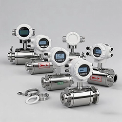 What is a Flowmeter?
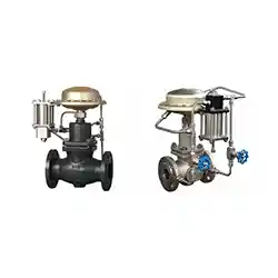 Difference Between Pilot Operated and Direct-Acting Self-operated Control Valve
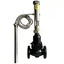 Classification of Self-Operated Control Valves
 What is a Plug Valve?