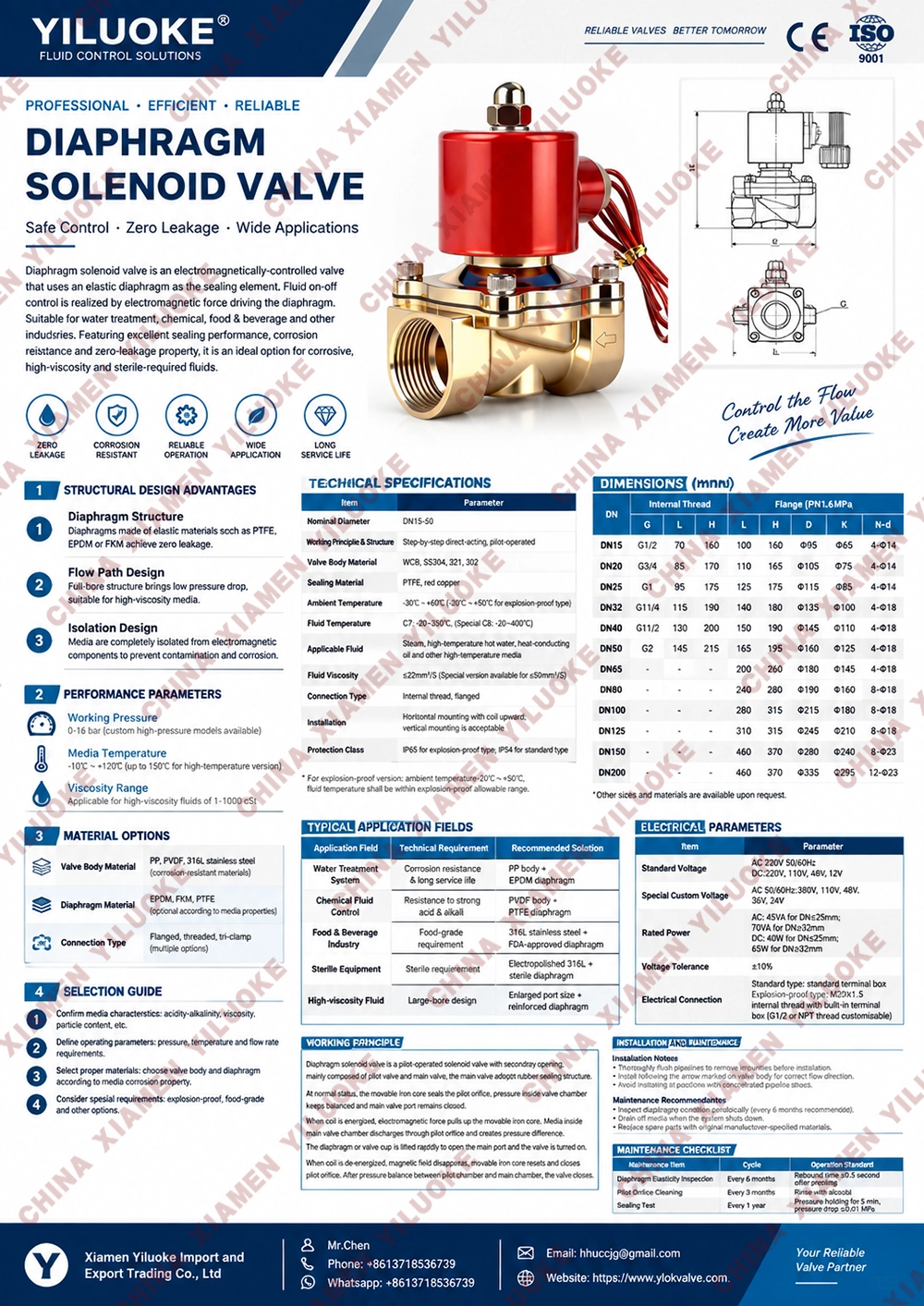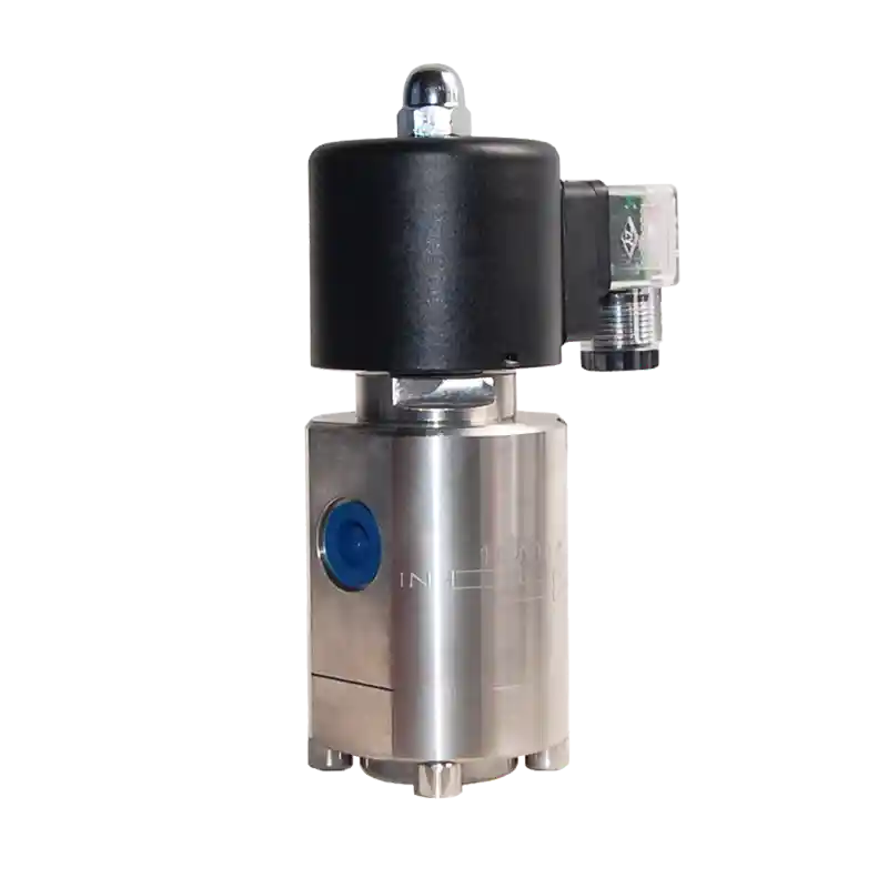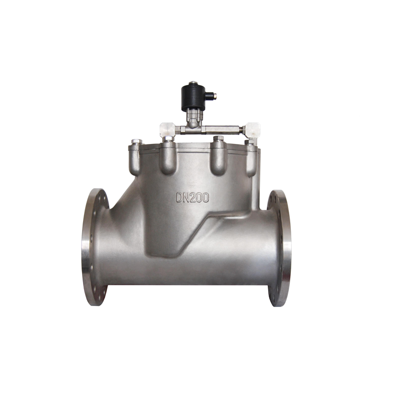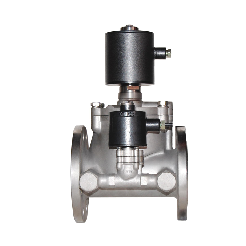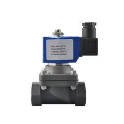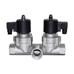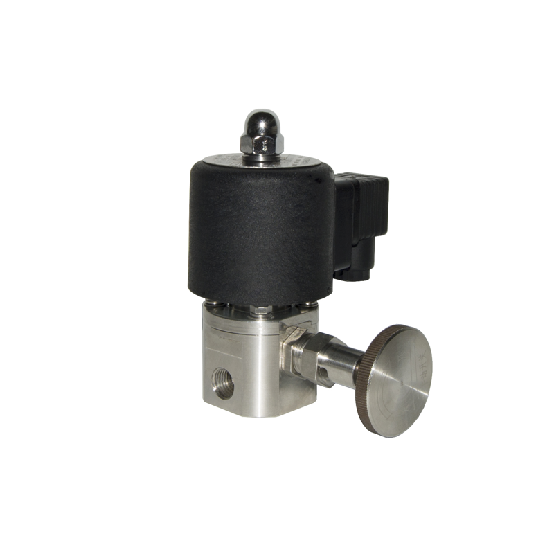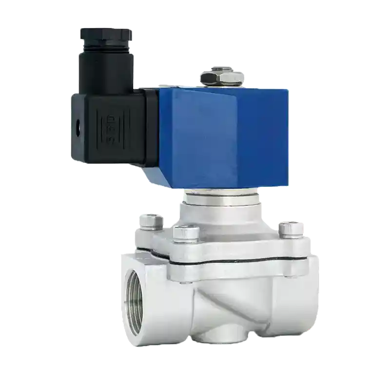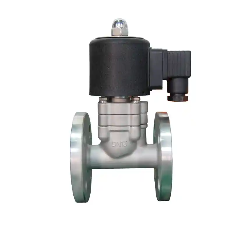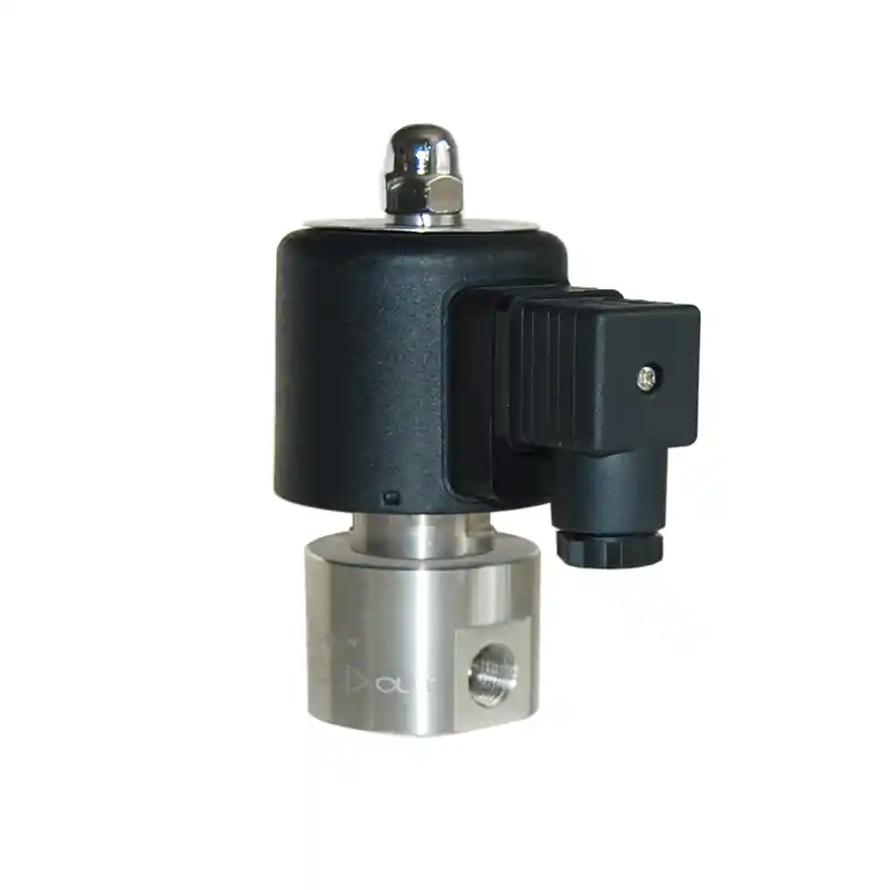


Diaphragm Type Solenoid Valves
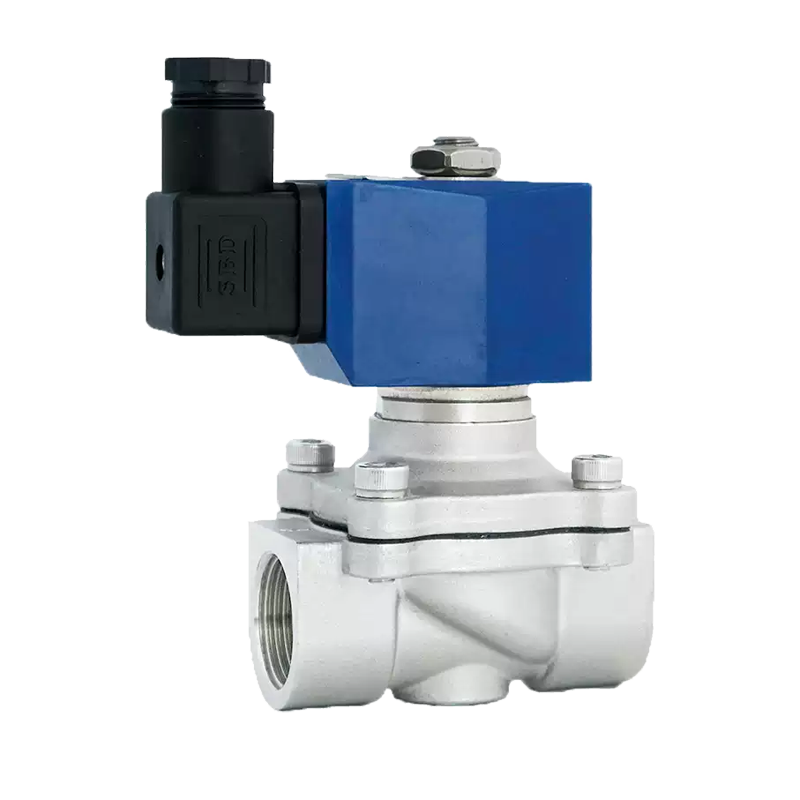
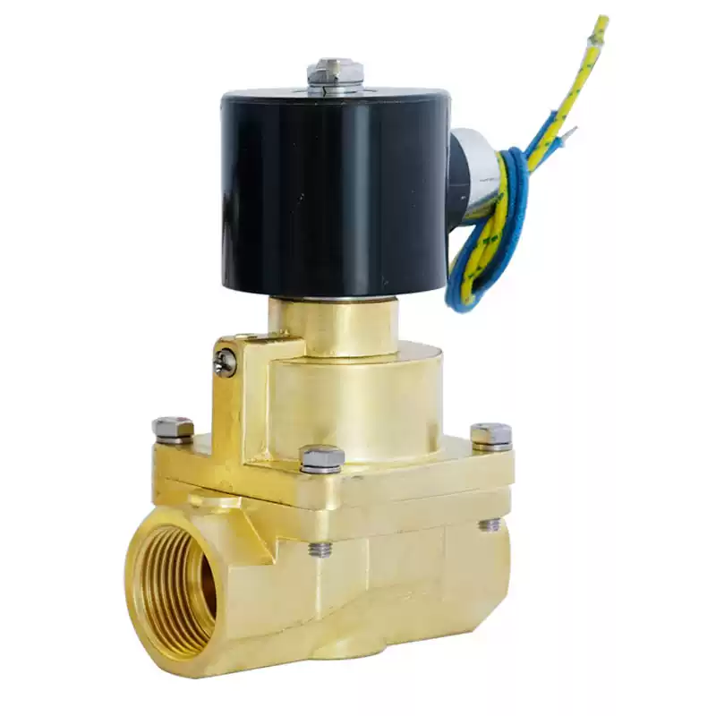
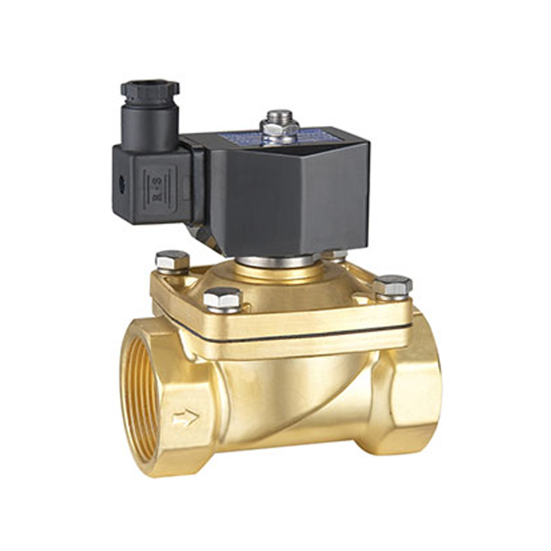
Diaphragm solenoid valves are suitable for media such as water, gas, steam and liquid. They can automatically or remotely control the on‑off of pipelines for working media including water, oil, liquid and air. Adopting rubber seal, the valve has low requirement on medium cleanliness, featuring fast opening‑closing action and high reliability.
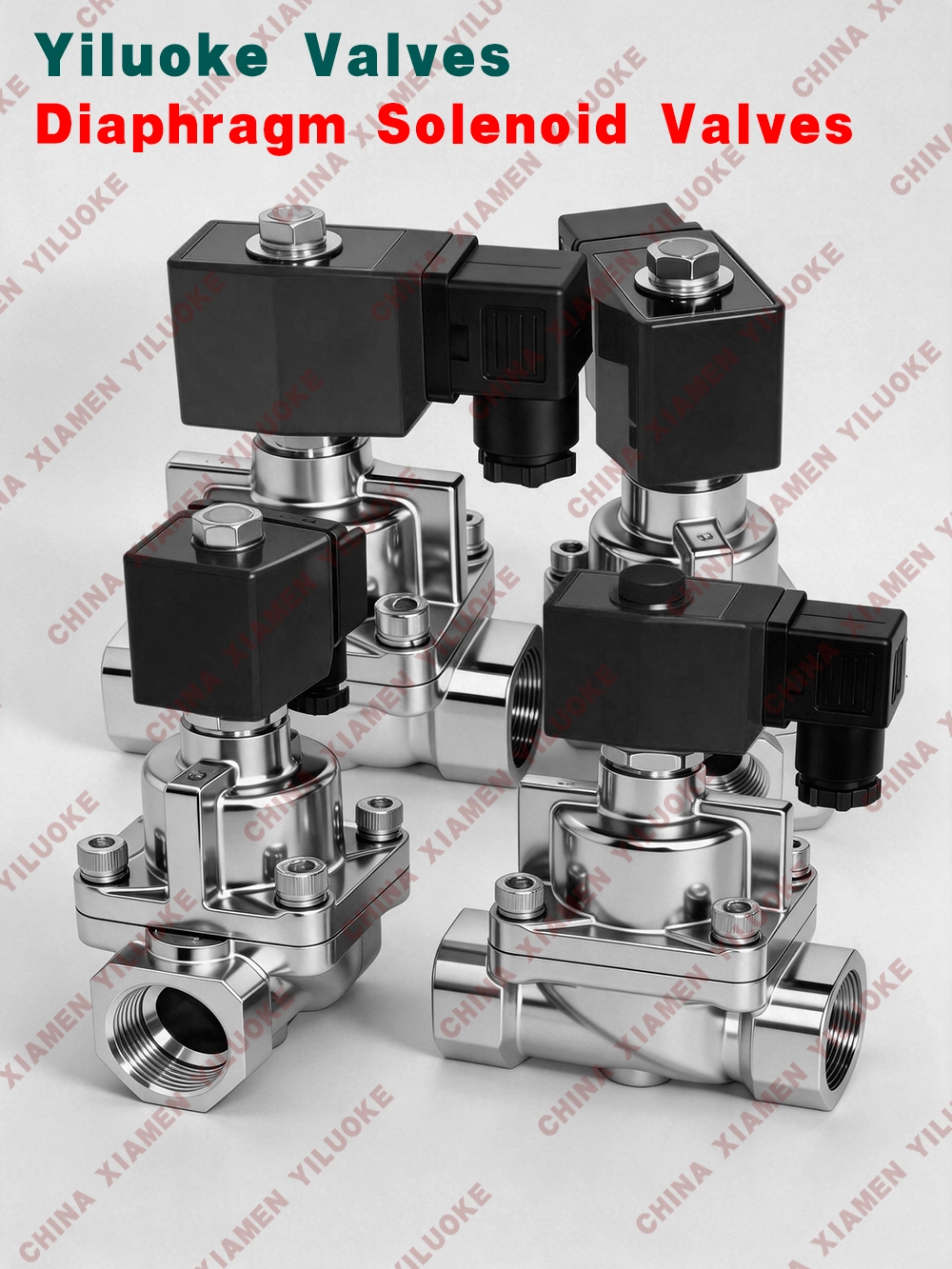
Structural Features of Diaphragm Solenoid Valve
1. Diaphragm‑type structure, low requirement for medium cleanliness
2. Flow coefficient increased by 10% compared with ordinary solenoid valves
3. Stable operation, low noise, no water hammer impact and no chattering
4. Compatible with mixed liquid and gas media, expanding application scope greatly
5. Sealed with imported synthetic rubber, service life more than 5 times of similar products, proven by 20‑year market practice
6. Special sealing structure together with imported synthetic rubber ensures zero leakage
Working Principle of Diaphragm Solenoid Valve
1. Basic Structural Composition
‑ Upper Chamber: Solenoid pilot system (coil, armature, spring)
‑ Middle Chamber: Pressure balance channel (pilot orifice / vent orifice)
‑ Lower Chamber: Flexible diaphragm plus valve seat (PTFE / EPDM and other materials)
2. Opening‑Closing Operation Cycle
Power‑on Opening: Electromagnetic force lifts pilot armature → upper chamber pressure vented → pressure difference generated across diaphragm → medium pressure lifts diaphragm.
Power‑off Closing: Pilot valve resets → upper chamber pressure rebuilt → pressure balanced on both sides of diaphragm → spring force compresses diaphragm for sealing.
3. Pressure Balance Mechanism
Realized by Φ0.5‑1mm pilot orifice:
‑ Valve opening: Upper‑chamber pressure : Lower‑chamber pressure = 3:1
‑ Valve closing: Pressure difference between upper and lower chamber ≤0.02MPa
Technical Characteristics
| Technical Characteristics | Implementation Method | Performance Parameters |
| Non‑polluting medium | Full‑flow PTFE lining | Low metal ion precipitation |
| Low‑differential‑pressure start‑up | Pilot‑operated pressure amplification | Minimum working differential pressure 0.05bar |
| Quick response | Light‑weight diaphragm design | Opening time ≤15ms |
| Long service life | Elastomer protection | High cycle life |
| Energy‑saving design | Pulse holding circuit | Power consumption ≤2.5W |
| Zero‑differential‑pressure operation | Dual‑diaphragm linkage structure | Operable under 0bar differential pressure |
Component Analysis
1. Diaphragm Material Selection
‑ PTFE composite diaphragm: Resistant to strong acid and alkali (pH 0‑14)
‑ FFKM perfluoroelastomer: Resistant to steam up to 200℃
‑ EPDM rubber: Cost‑effective solution for water treatment
2. Pilot Control Modes
1. Normally Open: Pilot orifice kept open when power off (for safety relief)
2. Normally Closed: Pilot orifice closed when power off (most common applications)
3. Bistable: Pulse trigger for switching (energy‑saving)
3. Pressure Compensation Design
Adopted stepped diaphragm structure:
‑ Small‑area central zone: Quick response
‑ Large‑area edge zone: Increased sealing force
Technical Parameters of Diaphragm‑type Steam Solenoid Valve
| Connection Size | 1/4”, 3/8", 1/2", 3/4", 1" |
| Nominal Pressure | 0.05MPa‑2.5MPa |
| Applicable Media | Steam, hot water, oil, ammonia gas, air, etc. |
| Applicable Temperature | PTFE: -60℃‑200℃ |
| Connection Thread | G thread, NPT thread |
| Optional Voltage | DC12V/24V, AC24V/120V, 240V/60Hz, 110V, 220V/50Hz (Tolerance: ±10%) |
| Valve Body | Stainless steel, brass |
| Seal Parts | PTFE |
| Magnetic Isolation Tube | 304 stainless steel |
| Moving Armature | 430F stainless steel |
| Static Armature | 430F stainless steel |
| Spring | 304 stainless steel |
| Shading Coil | Red copper |
Usage and Maintenance of Diaphragm Solenoid Valve
1. Assign dedicated personnel for operation and maintenance.
2. Annual regular inspection for 1‑2 times ensures reliable performance and long service life. The following four internal conditions will cause malfunction and shorten service life:
1) Medium property changed during operation;
2) Rust formed inside connecting pipes;
3) Oxidized compressor oil generates carbon particles and tar impurities entering pipelines;
4) Dust and dirt contaminants inside pipelines.
3. After installation or long‑term shutdown, perform several trial actuations with medium before formal operation.
4. Cut off power supply and release medium pressure before maintenance.
5. Do not disassemble coil assembly.
6. When disassembling and cleaning the solenoid valve, kerosene or trichloroethylene can be used. Please note rubber components may swell and shall be replaced if necessary.
7. Reassemble all components in original sequence after disassembly‑cleaning.