


Structural Design of Cryogenic Globe Valves
Cryogenic Globe Valves for Special Service
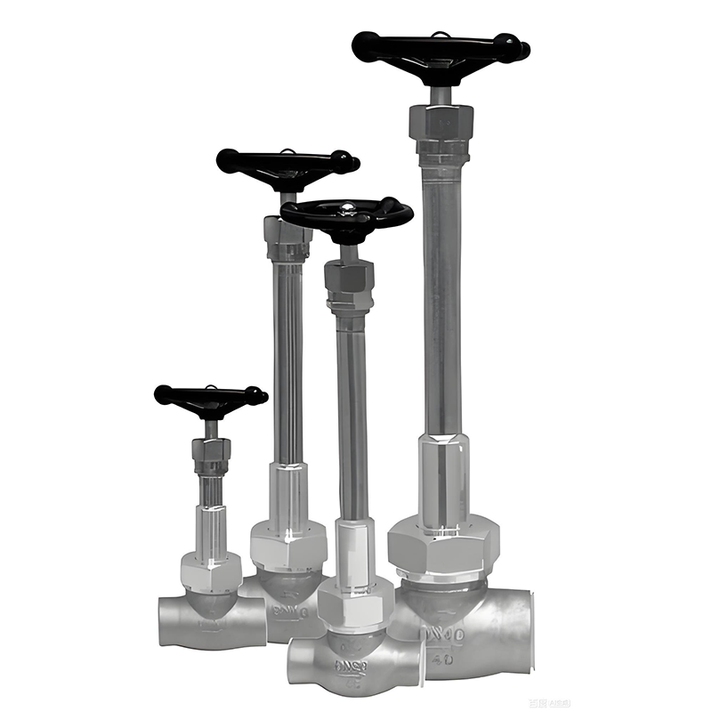
Cryogenic globe valves are one of the most commonly used types of globe valves. They mainly work in cryogenic gaseous hydrogen or liquid hydrogen media and are used as devices to open or close pipeline media. This article introduces a cryogenic globe valve used on a hydrogen-oxygen engine test bench. Aiming at the problem that the valve could not act during use, fault analysis was carried out, and the valve was able to operate normally in the test system by improving the structure.
2. Structural Characteristics
2.1 Technical Parameters
The technical parameters of the cryogenic globe valve are as follows:
Working medium: Cryogenic gaseous hydrogen, liquid hydrogen
Nominal diameter: 65mm
Maximum working pressure: 25MPa
Minimum working temperature: Liquid hydrogen temperature
Drive mode: Pneumatic (bidirectional air supply for cylinder)
Operating air source: Nitrogen, 5±0.2MPa
Connection mode: Flanged
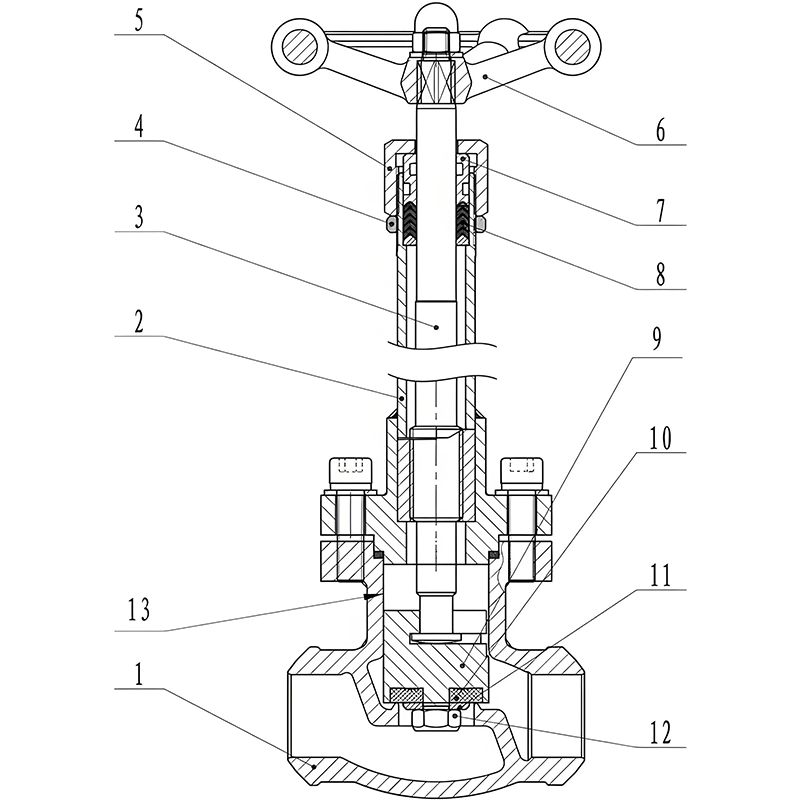
2.2 Structure
The cryogenic globe valve is composed of a valve body, a disc, a valve stem, a cylinder, etc. The valve body, valve bonnet, valve stem, etc. are all made of stainless steel, and the disc is made of copper. Epoxy phenolic laminated glass fiber cloth board is used between the upper and lower sections of the valve stem to achieve thermal insulation. The flange sealing surface adopts an aluminum gasket, the packing uses PTFE, and the cylinder uses double special seals to reduce friction. The entire valve adopts polyurethane foam insulation.
3. Design
3.1 Material Selection
Cryogenic propellants for aerospace rockets generally include liquid hydrogen, liquid oxygen, fluorine, etc. Therefore, valve materials are required to be low-temperature resistant, corrosion resistant, compatible with low-temperature media, and have relatively low thermal conductivity. At present, the widely used metal materials include austenitic steel, copper, aluminum, etc., and non-metallic materials include glass fiber reinforced plastic, PTFE, etc.
From a metallographic point of view, austenitic steel, copper, and aluminum with face-centered cubic lattices in metal materials will not experience low-temperature brittleness at low temperatures. However, due to the low hardness of aluminum and aluminum alloys, the wear resistance and scratch resistance of aluminum sealing surfaces are poor, so their use in low-temperature valves is limited, and they are only used in low-pressure and small-diameter valves.
Gaskets for low-temperature valves must have reliable sealing performance and resilience at room temperature, low temperature, and temperature changes. Therefore, gasket materials with small performance changes are generally selected. For example, asbestos packing impregnated with PTFE or molded plastic packing. Due to its very low thermal conductivity, glass fiber reinforced plastic is mostly used as a thermal bridge component.
3.2 Sealing Structure
In the design of the closing part, the valve seat is made of a harder material—stainless steel, and the disc is made of a softer material—copper. When austenite undergoes phase transformation at low temperatures, the sealing surface is uneven. The soft material deforms under the action of operating force to make it closely fit with the valve seat, compensating for material deformation caused by thermal stress and structural stress, and solving the sealing problem under high-pressure and low-temperature working conditions.
3.3 Thermal Insulation Structure
To better realize the thermal insulation of the cryogenic globe valve, the valve bonnet is designed into an elongated structure to lengthen the thermal bridge, preventing the valve stem at the stuffing box and the parts on the upper part of the valve bonnet from frosting due to excessive cooling of the stuffing box, which affects use. A heat insulation pad (material: epoxy phenolic laminated glass fiber cloth) is used to divide the valve stem into upper and lower parts to reduce heat flow and achieve thermal insulation. The entire valve adopts an external thermal insulation form, using polyurethane foam insulation with a thickness of 200mm.
4. Fault Analysis
After the cryogenic globe valve was applied to the test system, a fault of inability to act occurred. After disassembling the valve, it was found that the valve stem and the valve bonnet were seized. There were two deep scratches on the centerline symmetric position of the valve stem surface, and two scratches on the corresponding position of the lower flange of the matching valve bonnet. After analysis, there are two reasons for the fault.
(1) Storage period
During storage, the valve was placed horizontally and in an open state. The valve stem and disc formed a cantilever beam structure with a cantilever length of 147mm and a cantilever weight of 4.8kg. Due to gravity, the lower valve stem was bent, which increased the coaxiality deviation between the lower valve stem and the flange hole of the valve bonnet. In the original design, the maximum coaxiality deviation was 0.1mm, and the measured coaxiality deviation after removal was about 0.4mm. Since both parts are made of 0Cr18Ni9 stainless steel, lubrication cannot be performed at low temperatures, and seizure occurs due to large coaxiality deviation during operation.
(2) Processing period
After inspection, the pin groove on the valve bonnet was not processed according to the drawing (Figure 1). The square groove in the drawing was processed into an arc groove, which affected the normal fit between the pin and the pin groove. The lower valve stem was subjected to lateral force, resulting in interference between the lower valve stem and the valve bonnet.
5. Improvements
Aiming at the problems identified in the analysis, the structure of the cryogenic globe valve was improved.
(1) A H62 copper sleeve was pressed into the matching part of the valve stem and the valve bonnet at the φ51mm of the lower valve stem (Figure 2). The hardness of 0Cr18Ni9 stainless steel is 160HB, and the hardness of H62 brass is 56HB. This method can avoid seizure caused by direct contact of the same material. The φ51mm flange hole of the lower valve bonnet was processed to φ57mm, and a clearance fit (H8/f7) was adopted at the corresponding position of the lower valve stem, which not only ensures that the fitting parts have small dynamic friction force but also plays a guiding role.
(2) The function of the fit between the pin and the pin groove of the valve stem anti-rotation device is to prevent the valve stem from rotating. Since the disc, valve stem, cylinder, piston, etc. of the valve are rotating bodies, whether the valve stem rotates or not has no effect on its sealing and opening/closing performance. To avoid the lower valve stem being subjected to lateral force due to improper fit between the pin and the pin groove, the pin was removed.
6. Conclusion
The improved globe valve has good action performance in practical use. Generally speaking, stainless steel can be used for the moving pair of low-temperature valves when the clearance is appropriate, but it is prone to seizure when used for a long time under working conditions with lateral force or shaft deformation, so it should be avoided as much as possible. In addition, the valve should be placed and used vertically, and when not in use for a long time, the valve should be in a closed state.
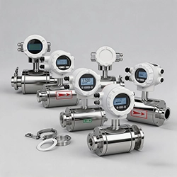 What is a Flowmeter?
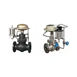 Difference Between Pilot Operated and Direct-Acting Self-operated Control Valve
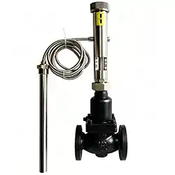 Classification of Self-Operated Control Valves
 What is a Plug Valve?