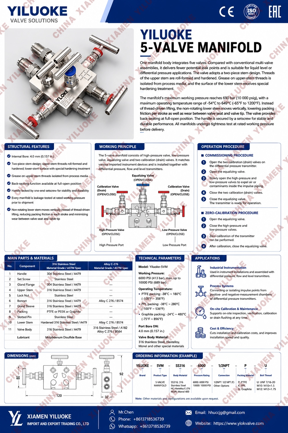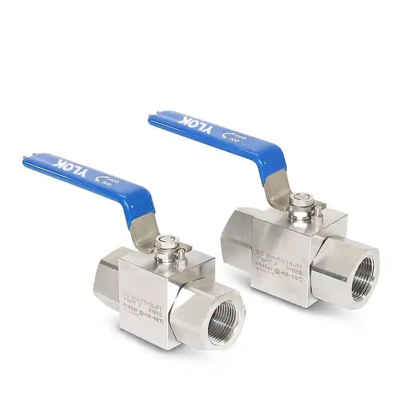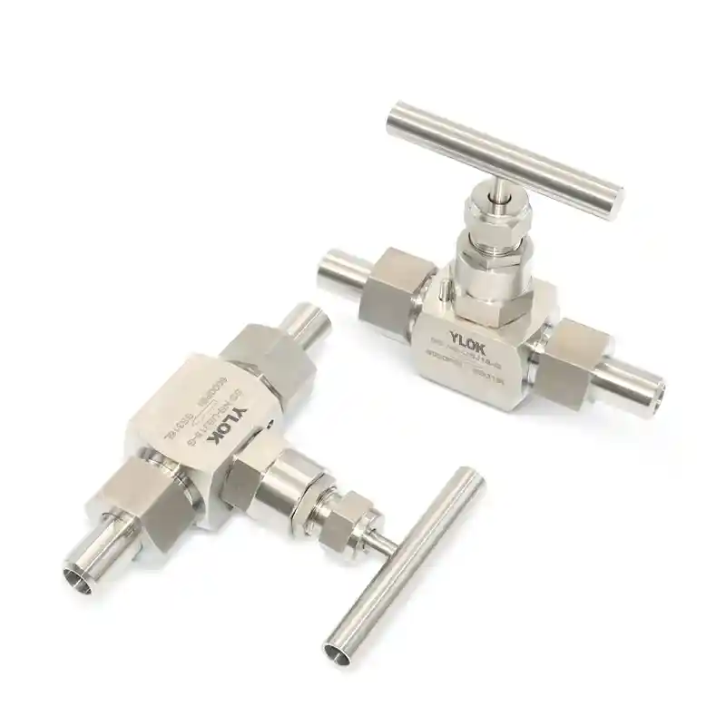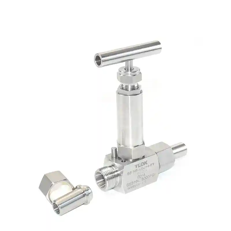


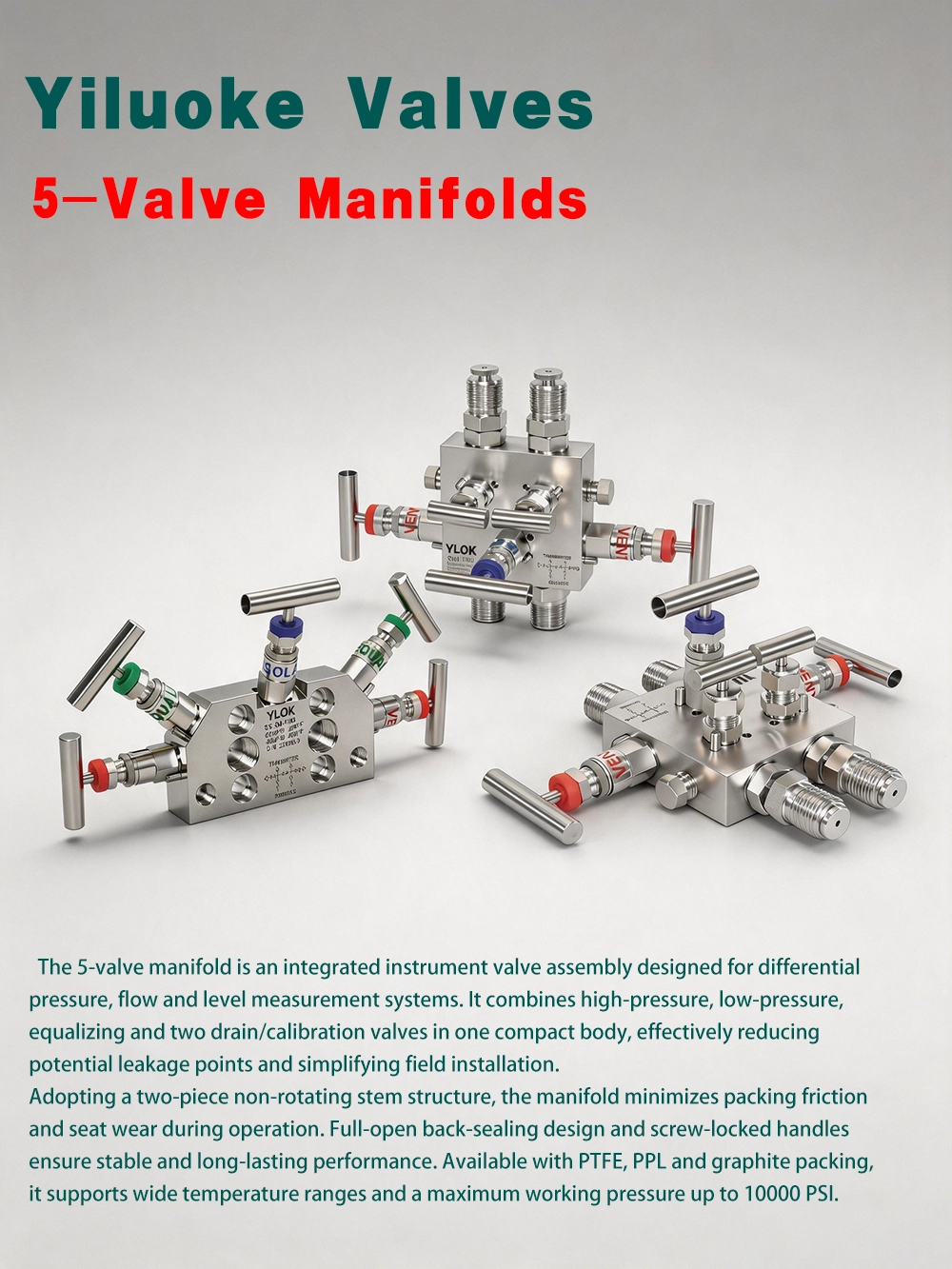
5-Valve Manifolds
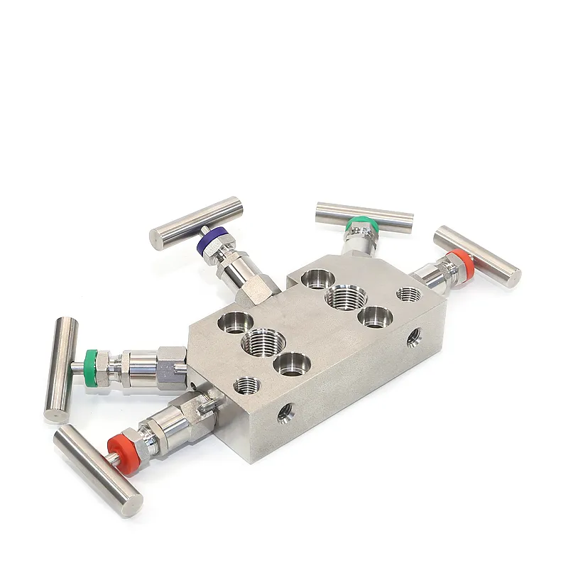
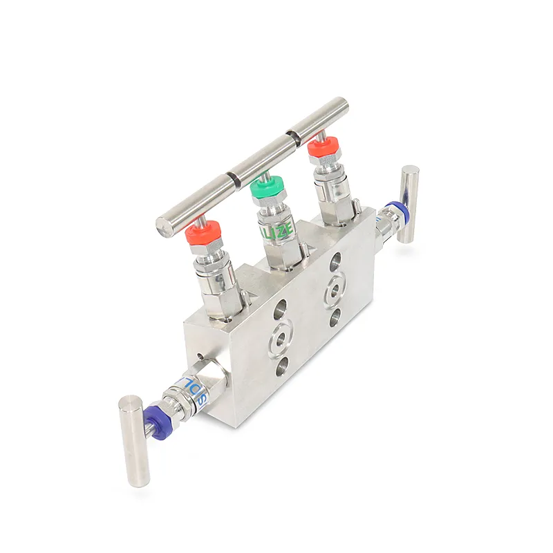
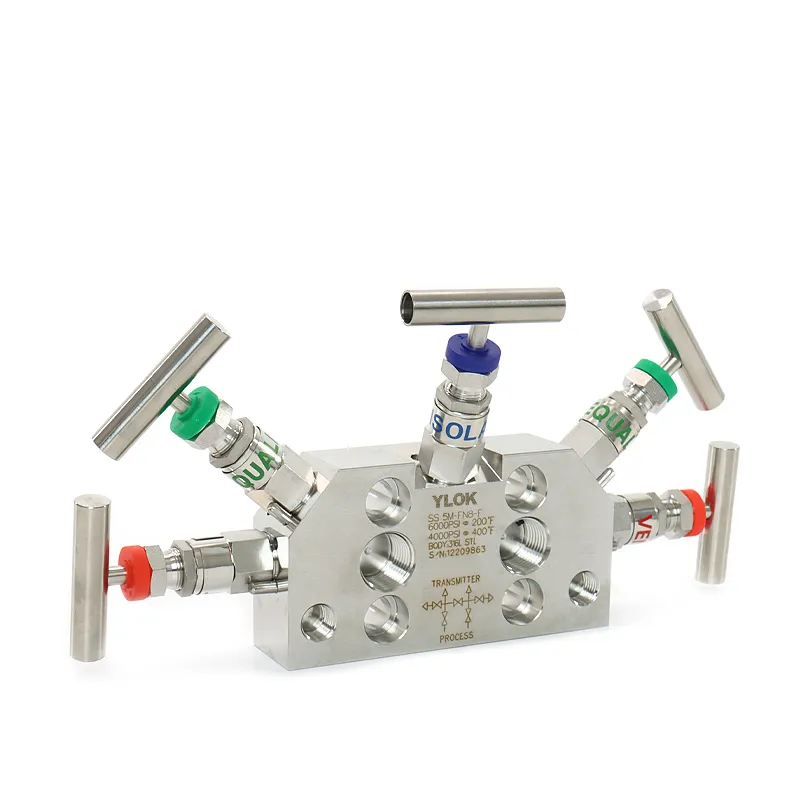
The 5 Valve Manifold consists of high‑pressure valve, low‑pressure valve, balance valve and two calibration (drain) valves. It features attractive appearance, compact structure and reliable sealing. It can be installed in supporting with various differential pressure / pressure transmitters and pressure instruments to realize opening, cutting off and discharging of fluid, as well as the control of flow, pressure, differential pressure and liquid level. It facilitates on‑site installation, commissioning, maintenance and inspection of instruments. The main structural types include flat type, T‑type, H‑type and column type. Working principle: Close the two calibration valves and balance valve during normal operation. For instrument calibration, cut off the high and low‑pressure valves, open the balance valve and two calibration valves, then close the balance valve to complete transmitter calibration and balancing.
5 Valve Manifold Selection Description
| Item | Parameter | Item | Parameter |
| Product Name | 5 Valve Manifold | Product Model | 56 |
| Nominal Diameter | 1/8"~1 1/2", special specifications customizable | Drive Mode | Manual |
| Connection Type | Ferrule connection, internal thread, socket weld, external thread, butt weld; other joint types are optional | ||
| Nominal Pressure | 6000Psi | Max Pressure | ≤10000Psi |
| Applicable Temperature | -70℃~+580℃ | Max Temperature | ≤800℃ |
| Applicable Medium | Gas, liquid and other fluids | Product Weight | 1KG~15KG |
| Valve Body Material | SS304, SS316, SS316L | Structure Type | Stop Type |
| Application Scenarios | Pressure transmitters, differential pressure transmitters, flow meters and other instruments | Brand Name | Xiamen Yiluoke |
| Test Pressure | 1.5 times of the maximum working pressure |
5 Valve Manifold Technical Parameters
Table 1 Parameters of Flat Type 5 Valve Manifold Yiluoke‑56
| Flat Type 5 Valve Manifold | Installation Scheme | Pressure | Material ASTM‑A276/A479 | Inlet Connection | Outlet Connection | Temperature | Mounting Bolt (304 Material) |
| Yiluoke‑56 | 0 General Specification | 3 32MPa | E 304 F 316 | N 1/2NPT | N 1/2NPT | L -40~230°C | E 7/16‑20UNF |
| 1 Rectangular inlet & outlet thread connection | 3 32MPa | D 316L G 316H | R Rc1/2 | R Rc1/2 | L -40~230°C | E 7/16‑20UNF | |
| 2 Inlet thread pitch 35mm | 3 32MPa | J 321 K 317L | M M20X1.5 | M M20X1.5 | L -40~230°C | E 7/16‑20UNF | |
| 3 Side inlet thread connection | 4 42MPa | M Monel H Hc‑276 | Custom special thread | W Flange IEC61518/DIN EN61518 | M 230~350°C | M M10X1.5 | |
| 4 Single balance valve with inlet & outlet thread connection | 4 42MPa | S S31803 Custom special material | Custom special thread | W Flange IEC61518/DIN EN61518 | M 230~350°C | M M10X1.5 | |
| 5 Double balance valve with inlet & outlet thread connection | 4 42MPa | Custom special material | Custom special thread | W Flange IEC61518/DIN EN61518 | M 230~350°C | M M10X1.5 |
Note: The code for all special options is 9. Example: JS5P9‑3999L‑E (flat type 5 Valve Manifold with special installation scheme, 32MPa pressure, special material and special inlet/outlet connection)
Table 2 Parameters of T‑Type 5 Valve Manifold Yiluoke‑56T
| T‑Type 5 Valve Manifold | Installation Scheme | Pressure | Material ASTM‑A276/A479 | Inlet Thread Connection | Outlet Connection | Temperature | Mounting Bolt (304 Material) |
| Yiluoke‑56T | 0 General specification, single balance valve | 3 32MPa | E 304 F 316 D 316L G 316H J 321 K 317L | N 1/2NPT R Rc1/2 M M20X1.5 | W Flange IEC61518/DIN EN61518 | L -40~230°C M 230~350°C | E 7/16‑20UNF |
| 1 Double balance valve | 4 42MPa | M Monel H Hc‑276 S S31803 Custom special material | Custom special thread | W Flange IEC61518/DIN EN61518 | M 230~350°C H 350~645°C | M M10X1.5 |
Note: The code for all special options is 9. Example: JS5T9‑3999L‑E (T‑type 5 Valve Manifold with special installation scheme, 32MPa pressure, special material and special inlet/outlet connection)
5 Valve Manifold Structural Characteristics
Integrated structure, safe and reliable
Equipped with stainless steel pins to prevent valve seat separation caused by vibration
Hard connection between valve seat and valve body to achieve reliable zero‑leakage sealing
Burr‑free thread and inner surface reduce leakage and ensure accurate instrument reading
Drawing dimension marks: 101MAX 3.1‑8.0s, 2‑1/4NPT, 32 2‑1/2NPT, 100 54 4‑12, 236MAX, 1801, 28.5, 59MAX, 180.1 3.195, 212MAX 100, 4‑3/16‑200KF, 113.mx, 54 3 5, 4‑12 through hole 59, 2‑1/4NPT 88 31.5, 124 68.5max, 240, sealing groove dimension
Valve body zoning: stop valve, drain valve, balance valve; divided into instrument end and process end
5 Valve Manifold Design Features
The valve tip adopts conical surface and rear ball head design, realizing low opening/closing torque and long service life
The valve stem sealing part is extruded with surface roughness Ra0.1, which reduces friction with packing and prolongs the service life of valve stem and packing
The valve body sealing port adopts self‑centering design to ensure the sealing line of valve tip is consistent during each closing
Blue, green and red colors are used to distinguish stop valve, balance valve and drain/test valve respectively for intuitive on‑site identification
Degreasing and Oil‑Free Treatment
For oxygen working conditions, valve groups and valves must undergo degreasing and oil‑free treatment. Otherwise, hydrocarbons and oil will react violently in oxygen, causing combustion and explosion. Selection instruction: Add suffix /T to the model code for oil‑free requirements. Special degreased joints shall be adopted if joints are required. Packaging: Products are packed in plastic sealing bags with "Oil‑Free" labels attached.
5 Valve Manifold Component Details
| No. | Component Description |
| 1 | Handle with anti‑loosening screws for better torque transmission |
| 2 | Color‑coded dust caps (blue, green, red) for distinguishing stop valve, balance valve and drain/test valve; prevents dust and impurities from entering the valve stem to avoid sealing failure |
| 3 | Gland nut: pushes and compresses packing to form sealing with valve stem and valve seat, allowing secondary and multiple adjustment for minor leakage |
| 4 | Rolled thread on valve stem improves surface hardness and wear resistance for longer service life |
| 5 | Lock nut provides reliable locking force to prevent gland nut loosening caused by vibration and subsequent sealing failure |
| 6 | Extruded valve stem sealing surface with Ra0.1 roughness reduces packing friction and extends service life |
| 7 | Metal washer provides non‑rotating thrust to reduce packing damage caused by rotational friction |
| 8 | Bottom‑mounted PTFE / flexible graphite packing prevents medium corrosion to valve stem threads |
| 9 | The back conical surface of valve stem forms linear contact with valve seat when fully open, providing auxiliary sealing |
| 10 | Duplex steel valve tip features high hardness to avoid damage after repeated use; rear ball head design provides non‑rotating pushing force; conical head forms linear sealing with valve body orifice; integral universal swing design eliminates hidden sealing risks caused by part misalignment |