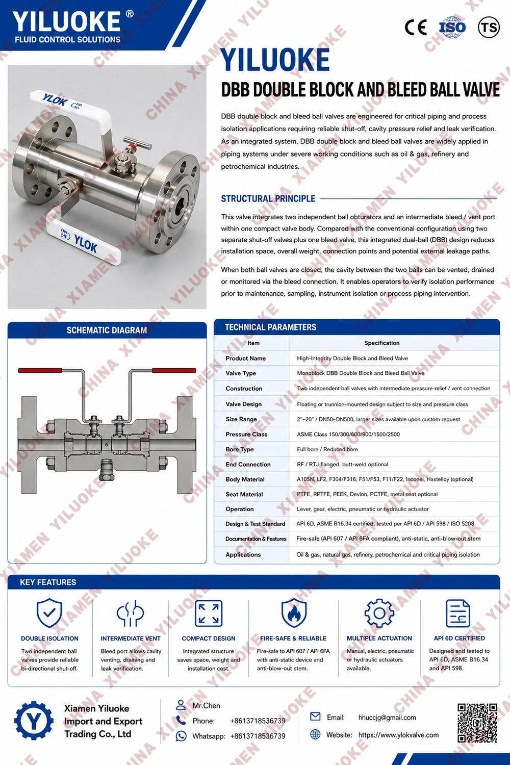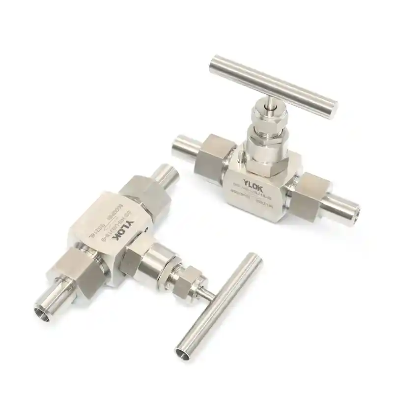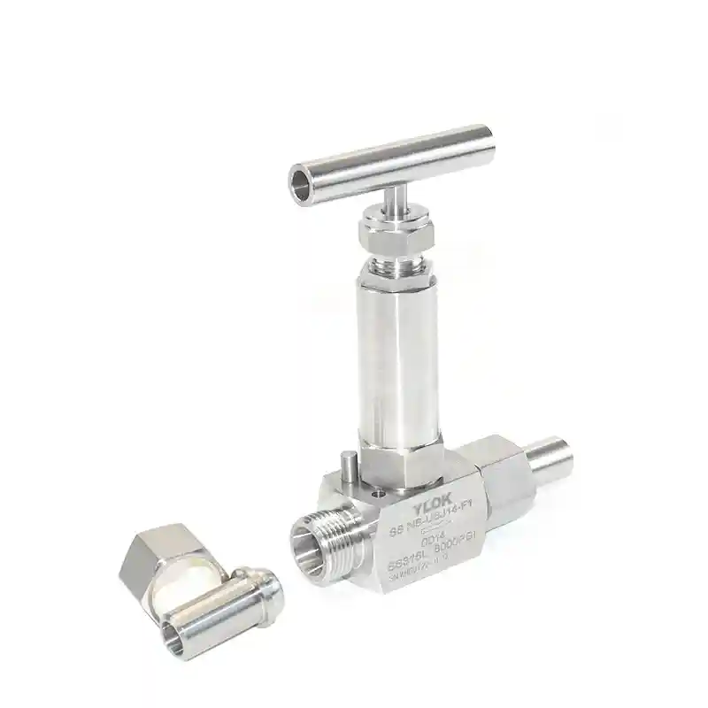


Double Block and Bleed Ball Valves
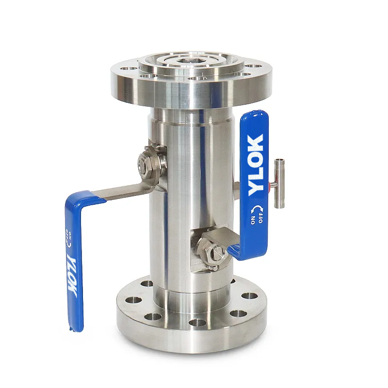
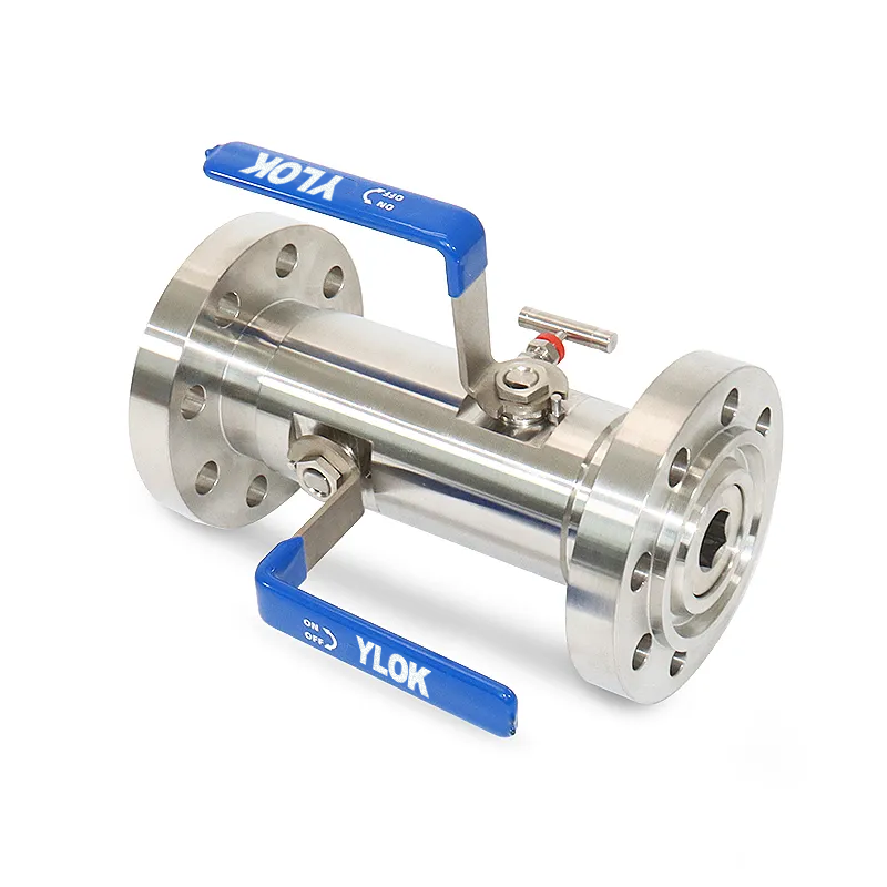
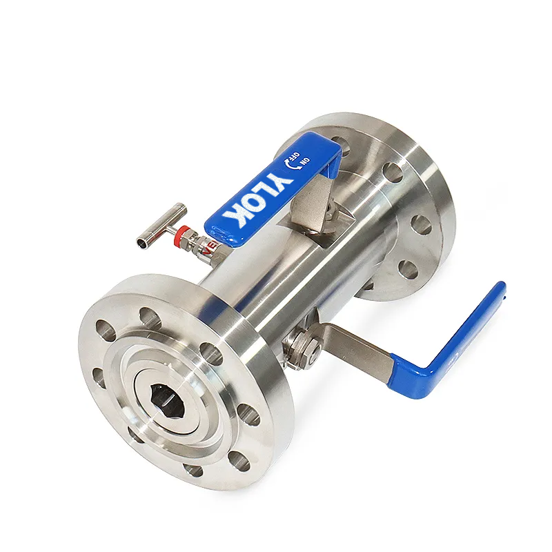
The DBB Ball Valve is equipped with two balls in one valve body. The two balls can be opened and closed simultaneously, or one open and one closed to realize double‑block‑and‑bleed function. It is divided into fixed ball and floating ball series. Featuring double block and bleed function, one valve body contains two balls, and the cavity between two balls is fitted with an external bleed valve (needle globe valve). It delivers reliable sealing performance and is suitable for occasions with strict sealing requirements where multiple valves are connected in series. The valve has two working states: both balls open or both balls closed. When the through‑hole of the ball aligns with the valve body passage, the valve is open. According to installation requirements, medium can enter from either end of the valve to realize pipeline fluid connection. When the driving device rotates the stem 90° clockwise to close the valve, two sealing pairs can simultaneously seal pressure from both ends, and medium trapped between two sealing pairs can be vented completely. This product replaces complex traditional pipeline solutions with multiple ball valves in series, reduces leakage points of pipeline system, realizes fast bleed and shut‑off, and provides excellent sealing performance.
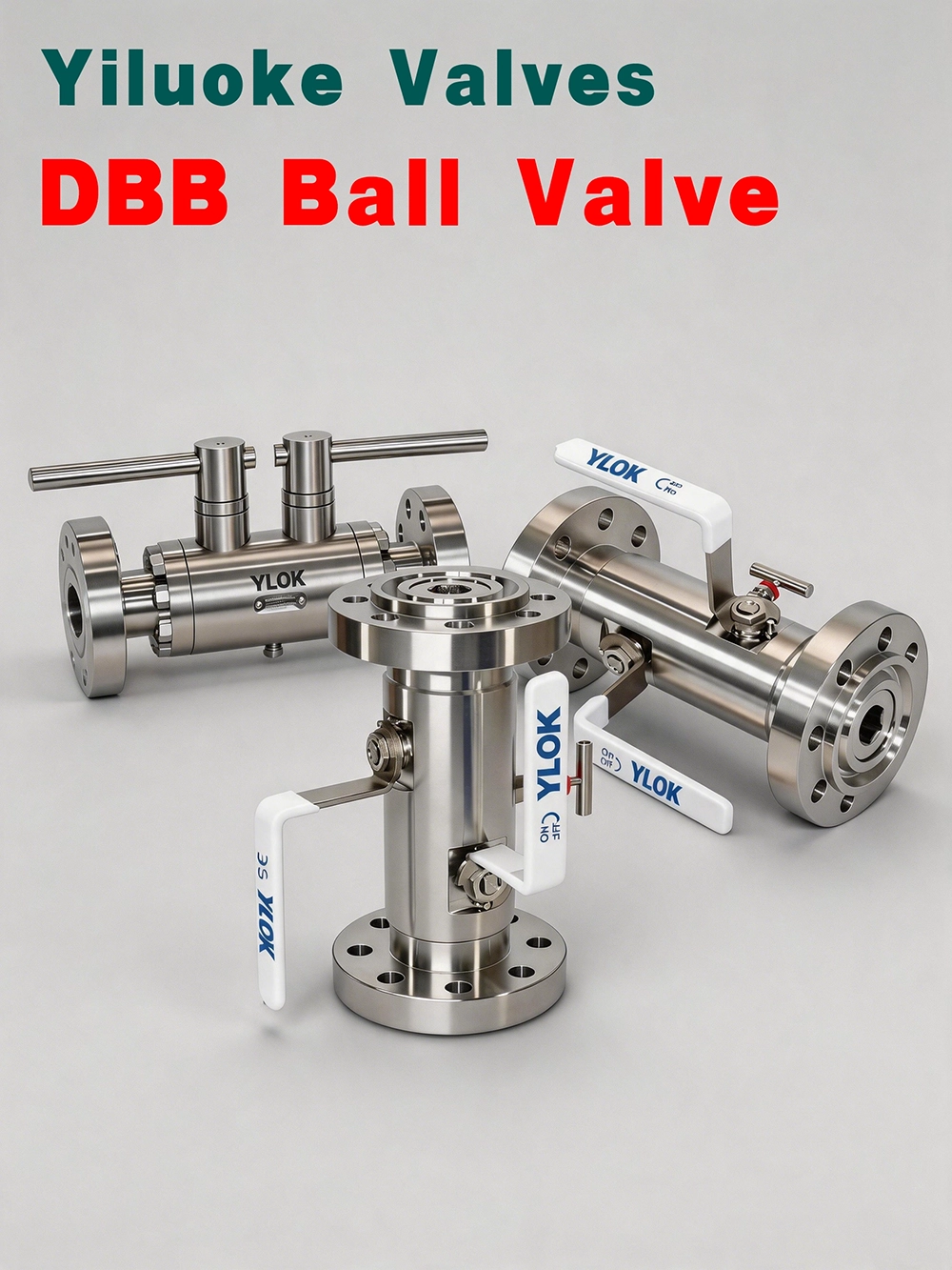
Structural Features
1. Fire‑safe structure. Upon customer request, the ball valve can be designed with fire‑safe construction. If sealing rings are damaged by fire, metal‑to‑metal hard sealing will be formed at all sealing positions to effectively prevent medium diffusion and restrain fire spread.
2. Lockable structure. Lock holes are provided at full‑open and full‑closed positions for valves installed in the wild, to prevent misoperation by unauthorized personnel or impact‑caused misoperation under heavy vibration. Padlocks can be fitted for safety protection.
3. Anti‑static structure. The ball valve can be built with anti‑static design. Conductive springs are installed between ball and stem, and between stem and valve body. Static electricity generated during valve operation will be conducted through static conductive path to pipeline and ground, eliminating static electricity. It avoids static spark ignition of flammable media and guarantees system safety.
Component Materials
| No. | Part Name | Materials |
| 1 | Connector | A105N, A182 F304, A182 F304L, A182 F316, A182 F316L |
| 2 | Valve Body | A105N, A182 F304, A182 F304L, A182 F316, A182 F316L |
| 3 | Bleed Valve | A105N, A182 F304, A182 F304L, A182 F316, A182 F316L |
| 4 | Valve Seat | RPTFE, PTFE, TEFLON, NYLON, PPL, PEEK, DEVLON, Stainless Steel + Hard Alloy |
| 5 | Ball | A105N+ENP, A182 F304, A182 F304L, A182 F316, A182 F316L |
| 6 | Valve Stem | A182 F6a, A182 F304, A182 F304L, A182 F316, A182 F316L |
| 7 | Gland | A105N, A182 F304, A182 F304L, A182 F316, A182 F316L |
| 8 | Packing | GRAPHITE, PTFE, TEFLON, PCTFE |
| 9 | Drain Valve | A105N, A182 F304, A182 F304L, A182 F316, A182 F316L |
| 10 | Stud | A193 B7, A193 B8, A193 B8, A193 B8, A193 B8 |
| 11 | Nut | A194 2H, A194 8, A194 8, A194 8, A194 8 |
Technical Parameters
| Item | Parameter | ||||
| Nominal Pressure Class | 150 | 300 | 600 | 900 | 1500 |
| Body Test Pressure (MPa) | 3.0 | 7.5 | 16.5 | 22.5 | 39.0 |
| High‑Pressure Liquid Seal Test Pressure (MPa) | 2.2 | 5.5 | 12.1 | 16.5 | 28.6 |
| Low‑Pressure Gas Seal Test Pressure (MPa) | 0.6 | 0.6 | 0.6 | 0.6 | 0.6 |
| Design & Manufacturing Standard | GB/T 12237, GB/T 21385, GB/T 19672, ASME B16.34, API 608, API 6D | ||||
| Face‑to‑Face Dimension | GB/T 12221, GB/T 19672, ASME B16.10, API 6D | ||||
| Flange Standard | JB/T 79, GB/T 9113, HG/T 20592, HG/T 20615, SH/T 3406, ASME B16.5, etc. | ||||
| Inspection & Test Standard | GB/T 26480, JB/T 9092, GB/T 13927, API 598, API 6D | ||||
General Technical Specifications
| Item | Parameter |
| Size Range | 1/2”~24”(15mm~600mm) |
| Temperature Range | -196℃~200℃(Actual operating temperature varies with material selection) |
| Pressure Class | 150‑2500 CLASS |
| Body Material | A105N, A182 F304, F304L, F316, F316L, A350 LF2, etc. |
| Design Standard | API 6D, ASME B16.34 |
| Face‑to‑Face | GB standard, ASME standard |
| End Connection | ASME B16.5, ASME B16.25, ASME B16.11 |
| Test Standard | API 6D, API 598, ISO 5208 |
| Operation Type | Handwheel, Worm gear |
| Application Fields | Petroleum, natural gas, chemical, power, petrochemical industries |
Additional Structural Features
Compact dimension and light weight reduce required installation space and supporting structure; provide inlet & outlet shut‑off, bleed and isolation function. Fire‑safe construction: flexible graphite packing or stainless steel graphite composite gaskets are adopted at potential leakage positions to meet fire‑safe requirements. Blow‑out‑proof stem structure allows on‑line packing replacement. Full‑port design facilitates pipeline pigging, featuring low flow resistance and high flow capacity.