


Cryogenic Ball Valves
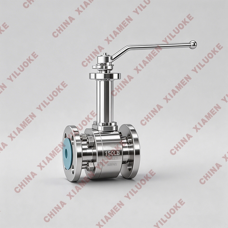
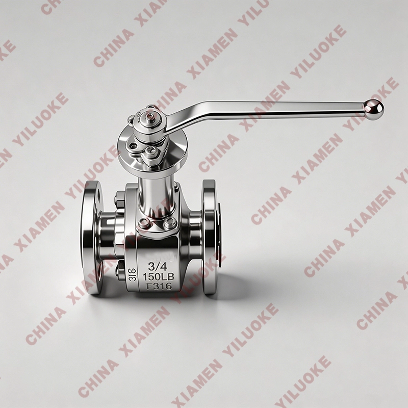
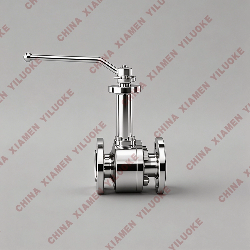
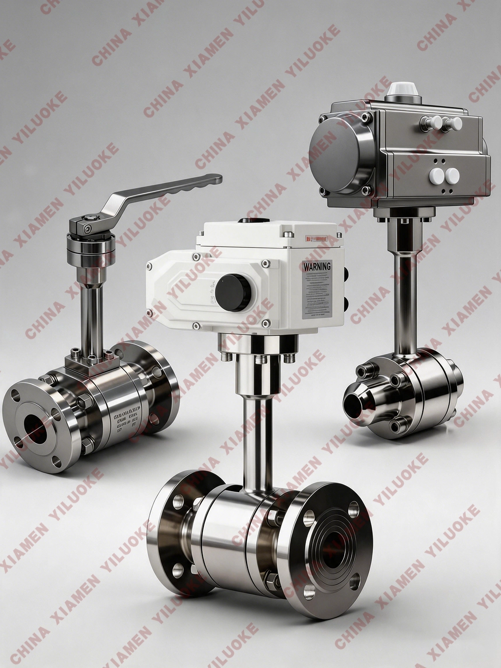
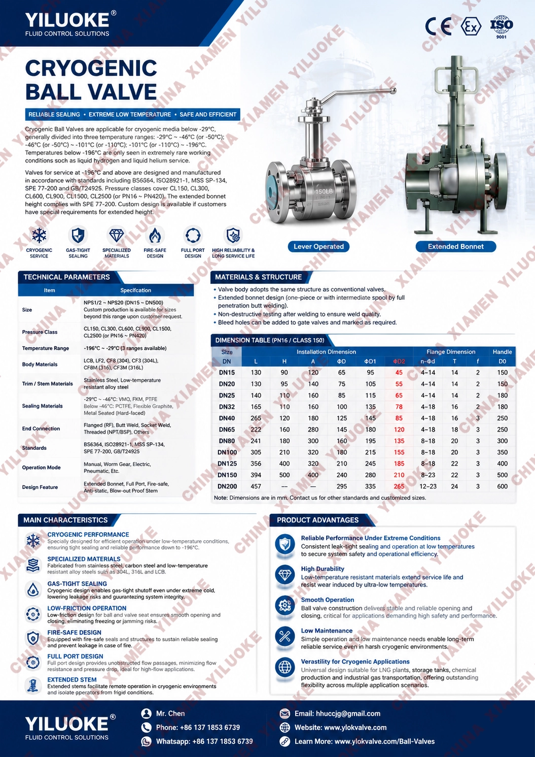
Cryogenic Ball Valves are suitable for various pipelines, used to cut off or connect media in the pipelines. By selecting different materials, they can be applied to different temperatures and media respectively, with a minimum operating temperature of -196℃. The actuation modes of Cryogenic Ball Valves include manual, worm gear drive, pneumatic or electric. Cryogenic Ball Valves generally adopt flange, welding or thread connection.
Features of Cryogenic Ball Valve
Sealing Performance Adopting special sealing structures and materials, it maintains reliable tightness under cryogenic conditions to prevent medium leakage.
Corrosion Resistance It is generally manufactured from corrosion-resistant materials such as stainless steel and chromium-molybdenum steel, enabling long-term service in harsh environments without corrosion.
Easy Operation Equipped with electric actuators, the ball valve can be opened and closed rapidly. It also supports remote control and automatic control conveniently.
Strong Adaptability It features impact resistance, temperature tolerance, seismic resistance and fire resistance, suitable for various complex working conditions.
Differences from Ordinary Ball Valves
| Characteristics | Cryogenic Ball Valve | Ordinary Ball Valve |
|---|---|---|
| Materials | Austenitic stainless steel, nickel-based alloys | Carbon steel, cast iron, etc. |
| Stem Length | Extended design for thermal insulation | Standard length |
| Sealing | Dual sealing with cryogenic compensation | Single sealing, no low-temperature adaptation |
| Test Standard | Cryogenic leakage test (e.g. -196℃) | Ambient temperature / high-pressure test |
Structural Design & Manufacturing Characteristics
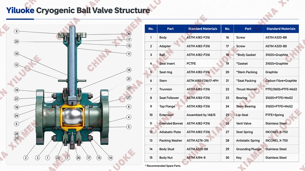
Cryogenic ball valves are divided into two types: cryogenic floating ball valves and cryogenic trunnion mounted ball valves. For operating temperatures higher than -50℃, the extended neck structure is generally not adopted. For ball valves working below -50℃, the standard neck length is set to 250mm.
Cryogenic ball valves are mainly used for transporting low-temperature liquid media including ethylene, liquid oxygen, liquid hydrogen, liquid nitrogen, liquid ammonia, liquid propane, liquefied natural gas (LNG) and liquefied petroleum products. These media are flammable and explosive, and will expand several times in volume when vaporized due to temperature rise, requiring strict low-temperature resistance and sealing performance of the valve.
Material Selection
Material selection is the core factor for liquefied natural gas valves. Unqualified materials will cause external or internal leakage of the valve body and sealing surface, and fail to meet the mechanical performance, strength and stiffness requirements under extreme low-temperature working conditions, which may even lead to component fracture and medium leakage, further causing explosion risks.
The main materials for valve body and bonnet are specified as below:
LCB: Applicable for working temperature down to -46℃
LC3: Applicable for working temperature down to -101℃
CF8 (304): Applicable for working temperature down to -196℃
Cryogenic Treatment Process
All self-produced cryogenic valves are treated with professional special cryogenic processing. Rough-machined parts are placed in cooling medium for 2 to 6 hours to release internal residual stress, stabilize the low-temperature mechanical properties of materials, ensure machining dimensional accuracy, and prevent valve deformation and leakage caused by temperature fluctuation under long-term cryogenic service conditions.
Technical Standards
| Item | Standard |
|---|---|
| Design Basis | GB Standard |
| Design Standard | GB12237-89 |
| Face-to-Face Dimension Standard | GB12221-89 |
| Flange Connection Standard | GB/T 9113-2000, JB/T79-94 |
| Inspection & Test Standard | JB/T 9092-99 |
Main Component Material Configuration & Temperature Range
| No. | Part Name | ASTM A352 LCB (≥-40℃) | ASTM A352 LC3 (≥-101℃) | ASTM F304(L) (≥-196℃) | ASTM F316(L) |
|---|---|---|---|---|---|
| 1-2 | Valve Body / Bonnet | A352 LCB | A352 LC3 | A182 F304(L) | A182 F304(L) |
| 3 | Stud Bolt | A193 L7 (Cadmium Plated) | A193 B8 | A193 B8 | A193 B8M |
| 4 | Nut | A194 L7 (Cadmium Plated) | A194 8 | A194 8 | A194 8M |
| 5,8 | Sealing Ring / Gasket | RTFE + Cu Powder / Nylon 1010 / PPL | RTFE + Cu Powder / Nylon 1010 / PPL | RTFE + Cu Powder / Nylon 1010 / PPL | RTFE + Cu Powder / Nylon 1010 / PPL |
| 6 | Ball | A182 F304 | A182 F304(L) | A182 F304(L) | A182 F316(L) |
| 7 | Valve Stem | A182 F304 | A182 F304(L) | A182 F304(L) | A182 F316(L) |
| 9,10 | Thrust Washer / Packing | RTFE + Cu Powder / Nylon 1010 / PPL / Carbon Fiber | RTFE + Cu Powder / Nylon 1010 / PPL / Carbon Fiber | RTFE + Cu Powder / Nylon 1010 / PPL / Carbon Fiber | RTFE + Cu Powder / Nylon 1010 / PPL / Carbon Fiber |
| 11 | Gland | A105N | A351 CF8 | - | - |
| 12 | Positioning Plate | A182 F321 | A182 F321 | A182 F321 | A182 F321 |
| 13 | Flat Nut | A194 4 (Cadmium Plated) | A194 8 | A194 8 | A194 8 |
| 14 | Handwheel | A193 L7 (Cadmium Plated) | A193 B8 | A193 B8 | A193 B8 |
| 15 | Cylindrical Pin | Q235A | Q235A | Q235A | Q235A |
Conventional Main Parts Material
Valve Body: 0Cr18Ni9
Ball: 0Cr18Ni9
Valve Stem: 0Cr18Ni9
Packing & Sealing Ring: PTFE
Product Dimension & Weight Specification (Model: DQ41F-40P)
Unit: mm
| Model | DN | L | H | D | D1 | D2 | D6 | Z-d | b | D0 |
|---|---|---|---|---|---|---|---|---|---|---|
| DQ41F | 15 | 130 | 180 | 95 | 65 | 45 | 40 | 4-14 | 16 | 140 |
| DQ41F | 20 | 150 | 220 | 105 | 75 | 55 | 51 | 4-14 | 16 | 160 |
| DQ41F | 25 | 160 | 230 | 115 | 85 | 65 | 58 | 4-14 | 16 | 180 |
| DQ41F | 32 | 180 | 310 | 135 | 100 | 78 | 66 | 4-18 | 18 | 200 |
| DQ41F | 40 | 200 | 320 | 145 | 110 | 85 | 76 | 4-18 | 18 | 200 |
| DQ41F | 50 | 230 | 400 | 160 | 125 | 100 | 88 | 4-18 | 20 | 250 |
| DQ41F | 65 | 290 | 420 | 180 | 145 | 120 | 110 | 8-18 | 22 | 320 |
| DQ41F | 80 | 310 | 500 | 195 | 160 | 135 | 121 | 8-18 | 22 | 320 |
| DQ41F | 100 | 350 | 520 | 230 | 190 | 160 | 150 | 8-23 | 24 | 360 |
| DQ41F | 125 | 400 | 600 | 270 | 220 | 188 | 176 | 8-25 | 28 | 500 |
| DQ41F | 150 | 480 | 620 | 300 | 250 | 218 | 204 | 8-25 | 30 | 700 |
| DQ41F | 200 | 600 | 720 | 375 | 320 | 282 | 260 | 12-30 | 38 | 900 |
Application Fields
Typical applications include liquefied natural gas (LNG) processing, cryogenic systems, aerospace, petrochemical industry, cryogenic engineering, refrigeration equipment, cold storage facilities, shipbuilding and offshore engineering. In these sectors, Cryogenic Ball Valves cut off or connect cryogenic media in pipelines to ensure safe, stable and efficient system operation.
How to Select a Proper Cryogenic Ball Valve?
(1) Material Selection
– Cryogenic toughness Main components including valve body and ball adopt austenitic stainless steel (304L, 316L etc.) or nickel-based alloys to avoid brittle fracture at low temperatures.
– Sealing materials Polytetrafluoroethylene (PTFE), reinforced graphite or special elastomers to retain elasticity under cryogenic service.
(2) Extended Stem Design
– Thermal insulation The stem is extended (normally 4–6 times the standard stem length) to keep the packing box and operating mechanism away from cryogenic zones and avoid frosting or freezing.
– Reduced heat conduction Minimize external heat ingress into the valve and prevent medium vaporization.
(3) Anti-leakage Structure
– Dual sealing Combination of primary metal-to-metal seal and secondary soft seal to guarantee sealing reliability at low temperatures.
– Special bonnet design Long-neck bonnet filled with thermal insulation materials (e.g. ceramic fiber) to reduce cold transfer.
(4) Pressure Relief Function
– Body cavity vent hole Prevent abnormal pressure rise inside the valve cavity caused by vaporization of warmed cryogenic medium, which may lead to hazards.
Typical Application Scenarios
– LNG transportation system Storage and transportation of liquefied natural gas (-162℃).
– Air separation equipment Medium control for liquid oxygen (-183℃), liquid nitrogen (-196℃), etc.
– Aerospace fuel systems Ultra-low-temperature environments with liquid hydrogen, liquid helium and other media.
Notes
– Pre-cooling operation Gradually pre-cool the valve before commissioning to avoid seal failure caused by thermal shock.
– Maintenance cycle Regularly inspect sealing performance to prevent material aging under low temperatures.
With the above designs, Cryogenic Ball Valves can operate stably under extreme temperatures and realize safe transportation and shutoff of process media.
Leave Your Message
Products categories
-
Cryogenic Pressure Regulator
-
Cryogenic Pneumatic Ball Valves
-
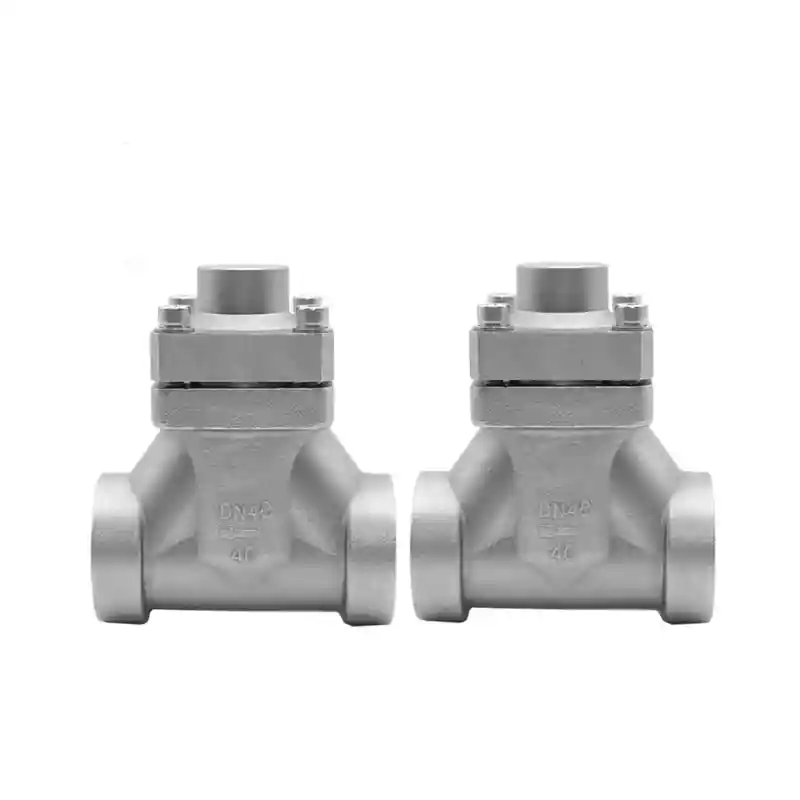
Cryogenic Check Valves
-
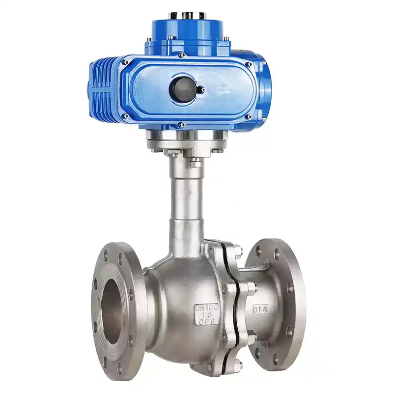
Cryogenic Electric Actuated Ball Valves
-
Cryogenic Ball Valves
-
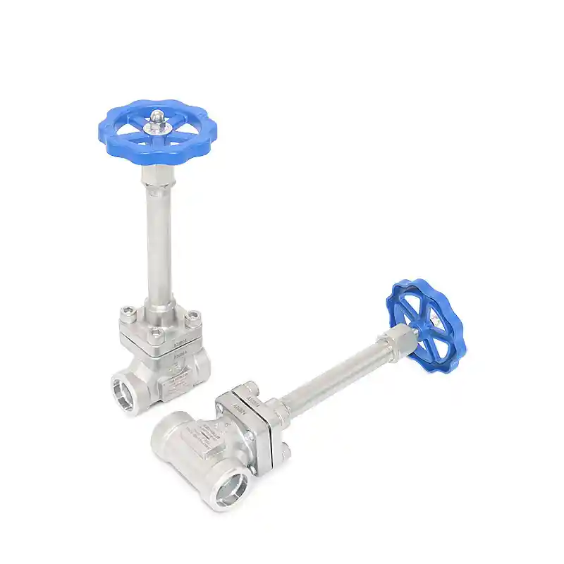
Cryogenic Extended Shaft Globe Valves
-
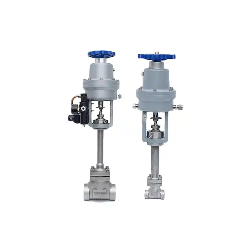
Cryogenic Pneumatic Emergency Shut-off Valves
-
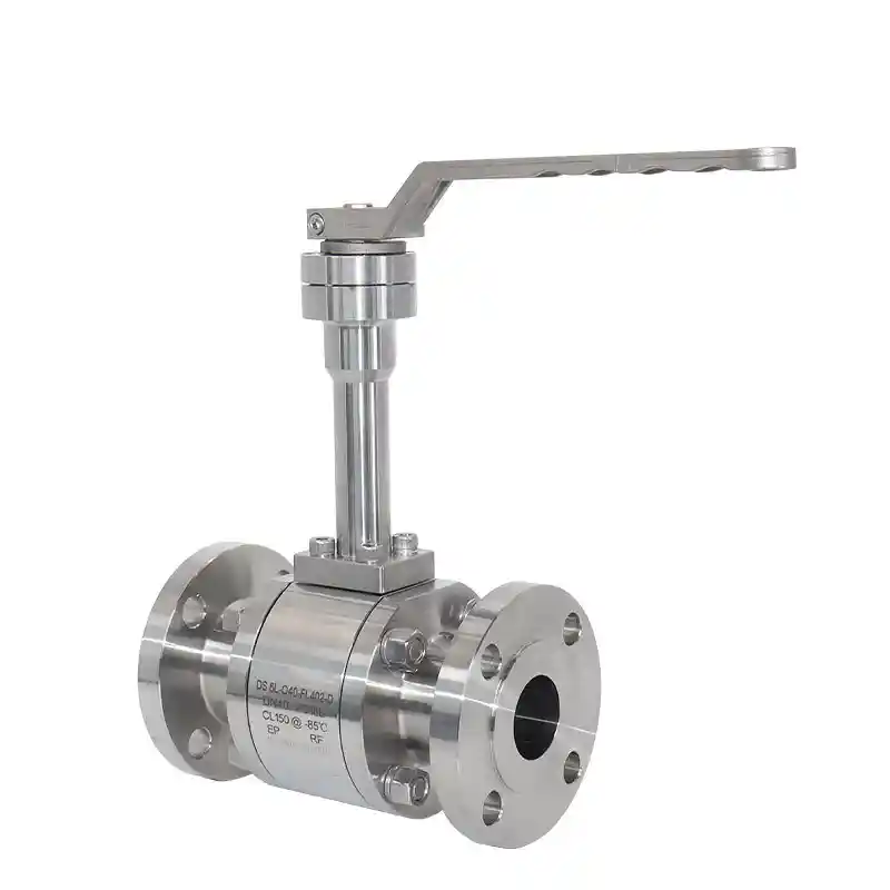
Cryogenic High-Pressure Ball Valve
-
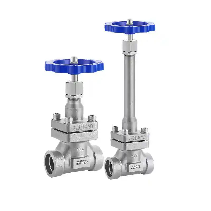
Cryogenic Globe Valves