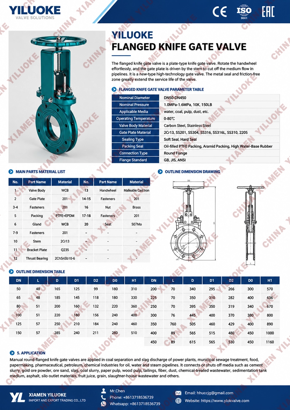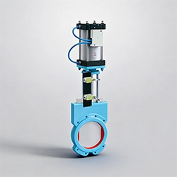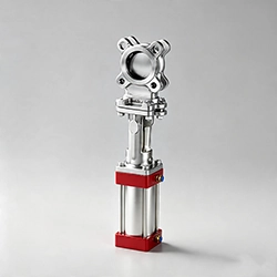


Flanged Knife Gate Valves
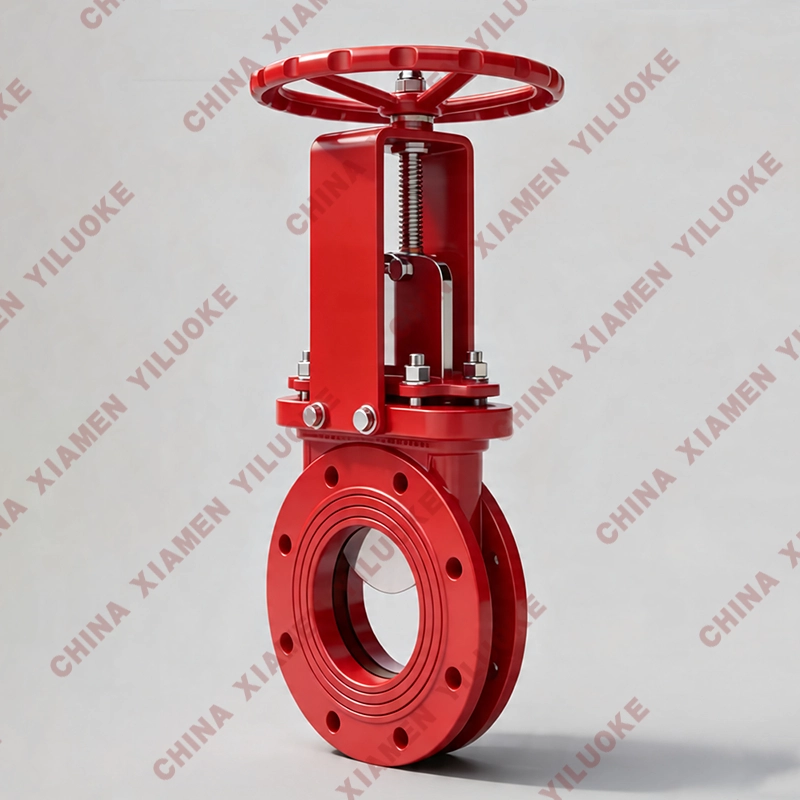
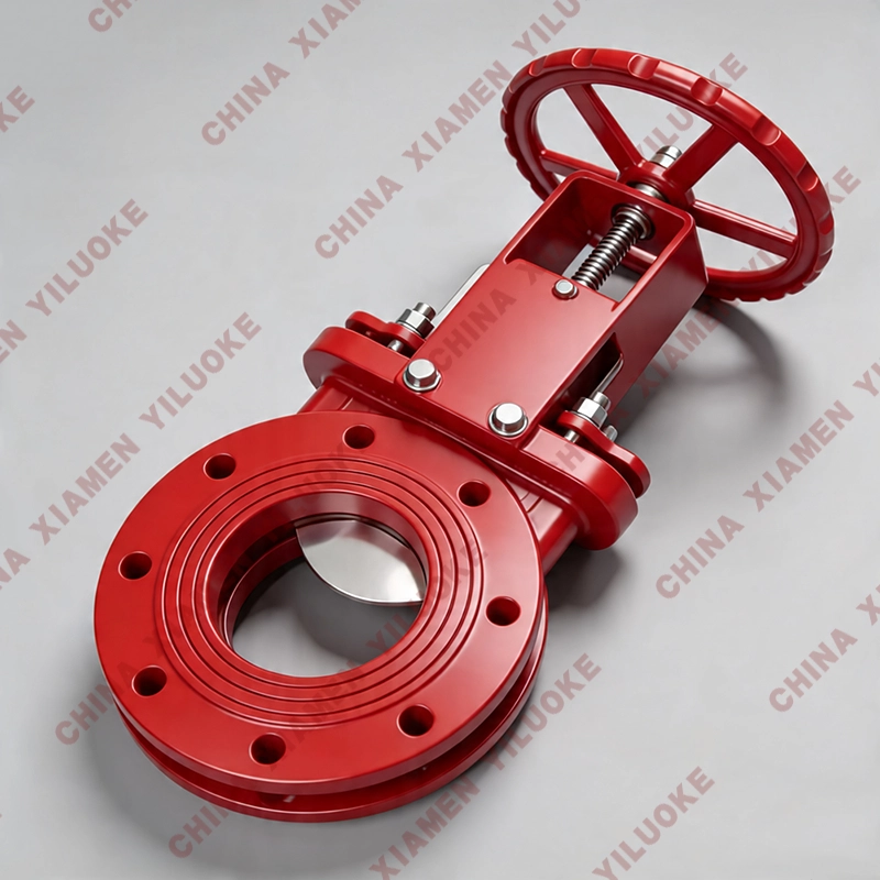
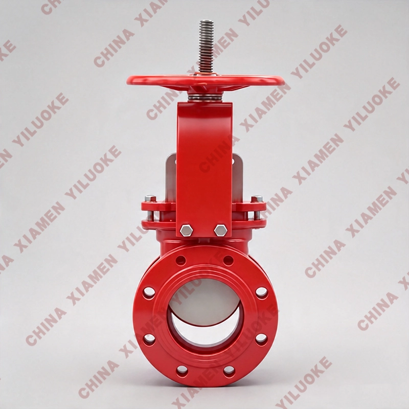
Flanged Knife Gate Valve adopts flanged connection type with short structural length to save materials. It greatly reduces the overall weight of the pipeline system and features convenient installation and maintenance. The gate plate works like a cutter to effectively cut off various impurities in the medium. The sealing ring material of this series knife gate valve can be selected from rubber, PTFE, stainless steel and hard alloy. It is widely applied in automatic process control systems of papermaking, mining, metallurgy, chemical industry, power supply, municipal sewage treatment and other fields. Applicable media include pulp, sewage, coal slurry, ash‑water mixture, slag‑water mixture and other working fluids.
Product Features
1. The valve adopts integrated design with low fluid resistance for flexible and convenient operation.
2. The screw drive of manual knife gate valve is equipped with double‑plane bearing structure, which greatly reduces transmission friction and enables light and smooth valve opening.
3. The knife gate valve is fitted with movable sealing seat. Pre‑tightening force provided by O‑ring makes the sealing seat closely fit against the gate plate to minimize leakage. It provides automatic compensation for wear of sealing pairs during long‑term service and extends service life.
4. Fixed guiding claws and groove‑free structure prevent medium accumulation and jamming.
5. The valve seat supports metal hard‑seal or soft‑seal options according to media and working conditions. The gate plate is treated with surface chrome‑plating or ion nitriding for better wear resistance and longer service life of sealing surface. Soft‑seat options include PTFE seat, reinforced PTFE seat, EPDM and NBR rubber with good sealing performance and corrosion resistance.
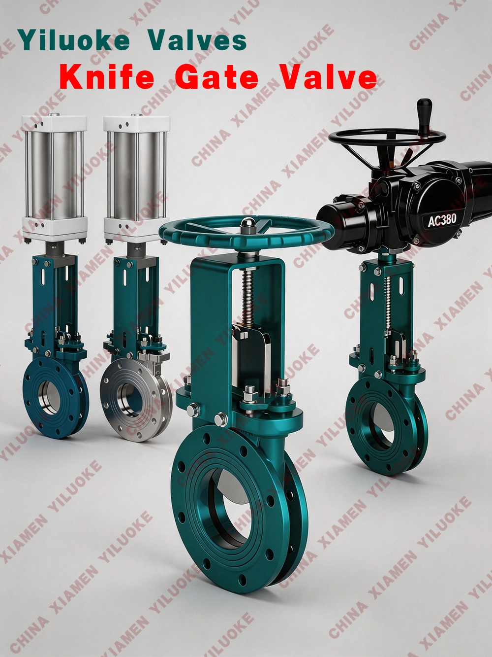
6. Wide medium adaptability. It delivers reliable sealing performance and high cost‑effectiveness. Manual, pneumatic and electric operation modes are available for extensive application scenarios.
Main Parts Material
| Valve Body & Upper Cover | Carbon Steel, Stainless Steel |
| Gate Plate | Stainless Steel |
| Stem | Stainless Steel |
| Sealing Ring | Rubber, PTFE, Stainless Steel, Hard Alloy |
Performance Specification
| Nominal Pressure | PN |
| Body Test | 1.5×PN |
| Sealing Test | 1.1×PN |
| Working Temperature | Rubber seal ≤80℃, PTFE seal ≤180℃, Hard seal ≤425℃ |
| Applicable Medium | Syrup, pulp, sewage, coal slurry, ash‑water mixture, slag‑water mixture |
Overall & Connection Dimensions (mm)
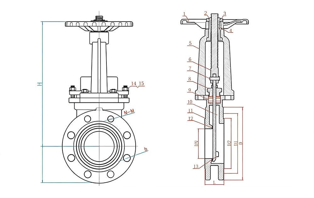
| MPa | DN | L | D | D1 | D2 | H | N‑M | D0 |
| 1.0 | 50 | 50 | 160 | 125 | 100 | 330 | 4‑M16 | 180 |
| 1.0 | 65 | 50 | 180 | 145 | 120 | 360 | 4‑M16 | 180 |
| 1.0 | 80 | 50 | 195 | 160 | 135 | 390 | 4‑M16 | 220 |
| 1.0 | 100 | 50 | 215 | 180 | 155 | 440 | 8‑M16 | 220 |
| 1.0 | 125 | 50 | 245 | 210 | 185 | 510 | 8‑M16 | 230 |
| 1.0 | 150 | 60 | 280 | 240 | 210 | 600 | 8‑M20 | 280 |
| 1.0 | 200 | 60 | 335 | 295 | 265 | 700 | 8‑M20 | 360 |
| 1.0 | 250 | 70 | 390 | 350 | 320 | 840 | 12‑M20 | 360 |
| 1.0 | 300 | 80 | 440 | 400 | 368 | 960 | 12‑M20 | 400 |
| 1.0 | 350 | 90 | 500 | 460 | 428 | 1110 | 16‑M20 | 400 |
| 1.0 | 400 | 100 | 565 | 515 | 482 | 1250 | 16‑M22 | 400 |
| 1.0 | 450 | 114 | 615 | 565 | 532 | 1380 | 20‑M22 | 530 |
| 1.0 | 500 | 114 | 670 | 620 | 585 | 1530 | 20‑M22 | 530 |
| 1.0 | 600 | 115 | 780 | 725 | 685 | 1800 | 20‑M27 | 600 |
| 1.0 | 700 | 165 | 895 | 840 | 800 | 2150 | 24‑M27 | 600 |
| 1.0 | 800 | 180 | 1010 | 950 | 898 | 2420 | 24‑M30 | 680 |
| 1.0 | 900 | 190 | 1110 | 1050 | 1005 | 2680 | 28‑M30 | 680 |
| 1.0 | 1000 | 200 | 1220 | 1160 | 1115 | 3100 | 28‑M30 | 700 |
| 1.0 | 1200 | 254 | 1450 | 1380 | 1325 | 3450 | 32‑M36 | 800 |
PN1.6Mpa Manual Wafer‑Type Knife Gate Valve Dimension Table:
| MPa | DN | L | D | D1 | D2 | H | N‑M | D0 |
| 1.6 | 50 | 50 | 160 | 125 | 99 | 330 | 4‑M16 | 180 |
| 1.6 | 65 | 50 | 185 | 145 | 120 | 360 | 4‑M16 | 180 |
| 1.6 | 80 | 50 | 200 | 160 | 135 | 390 | 8‑M16 | 220 |
| 1.6 | 100 | 50 | 220 | 180 | 155 | 440 | 8‑M16 | 220 |
| 1.6 | 125 | 50 | 250 | 210 | 185 | 510 | 8‑M16 | 230 |
| 1.6 | 150 | 60 | 285 | 240 | 210 | 600 | 8‑M20 | 280 |
| 1.6 | 200 | 60 | 340 | 295 | 265 | 700 | 12‑M20 | 360 |
| 1.6 | 250 | 70 | 405 | 355 | 310 | 840 | 12‑M22 | 360 |
| 1.6 | 300 | 80 | 460 | 410 | 375 | 960 | 12‑M22 | 400 |
| 1.6 | 350 | 90 | 520 | 470 | 435 | 1110 | 16‑M22 | 400 |
| 1.6 | 400 | 100 | 580 | 525 | 485 | 1250 | 16‑M27 | 400 |
| 1.6 | 450 | 114 | 640 | 585 | 545 | 1380 | 20‑M27 | 530 |
| 1.6 | 500 | 114 | 715 | 650 | 609 | 1530 | 20‑M30 | 530 |
| 1.6 | 600 | 115 | 840 | 770 | 720 | 1800 | 20‑M36 | 600 |
| 1.6 | 700 | 165 | 910 | 840 | 788 | 2150 | 24‑M36 | 600 |
| 1.6 | 800 | 180 | 1025 | 950 | 898 | 2420 | 24‑M36 | 680 |
| 1.6 | 900 | 190 | 1125 | 1050 | 998 | 2680 | 28‑M36 | 680 |
| 1.6 | 1000 | 200 | 1255 | 1170 | 1110 | 3100 | 28‑M42 | 700 |
| 1.6 | 1200 | 254 | 1485 | 1390 | 1325 | 3450 | 32‑M48 | 800 |
Installation and Operation
1. Installation position, height and flow direction shall comply with design requirements, and connections shall be firm and tight.
2. For manual valves installed on thermal‑insulated pipelines, the handwheel shall not face downward.
3. Visual inspection shall be carried out before installation. Valve nameplate shall comply with GB standard Marking of General Valves GB1220. Valves with nominal pressure above 1.0MPa for main pipeline shut‑off service shall pass strength and tightness test before installation. For strength test, test pressure shall be 1.5 times nominal pressure and hold no less than 5 minutes with zero leakage on valve body and packing. For tightness test, test pressure shall be 1.1 times nominal pressure. Pressure shall meet GB50243 requirements during test duration with no leakage on gate sealing face.
4. Do not lift by handwheel, handle or transmission mechanism. Avoid heavy impact.
5. Gate valves with transmission mechanism shall be installed in accordance with product operation manual.