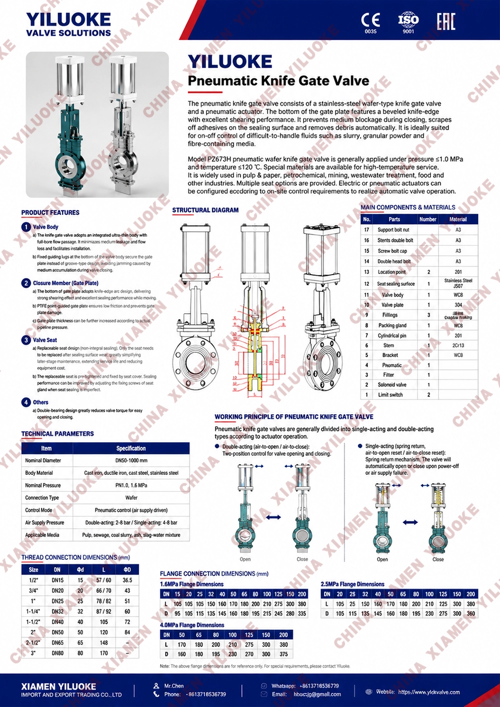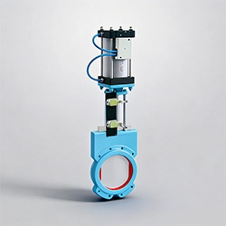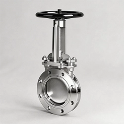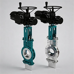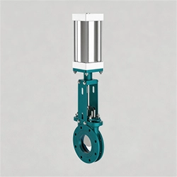


Pneumatic Knife Gate Valve
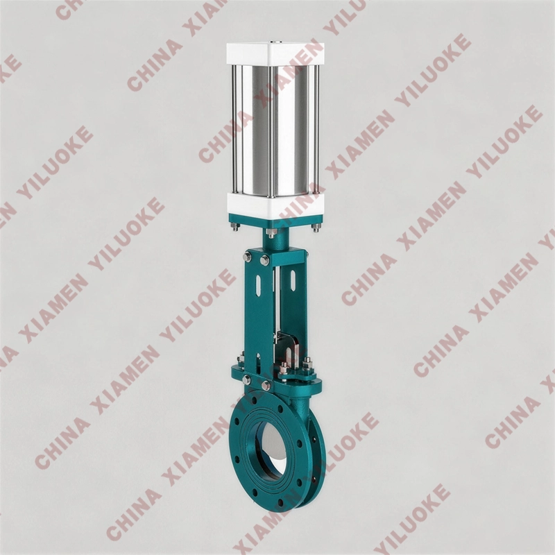
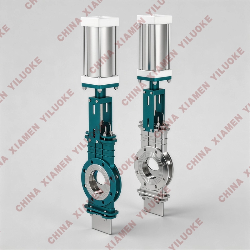
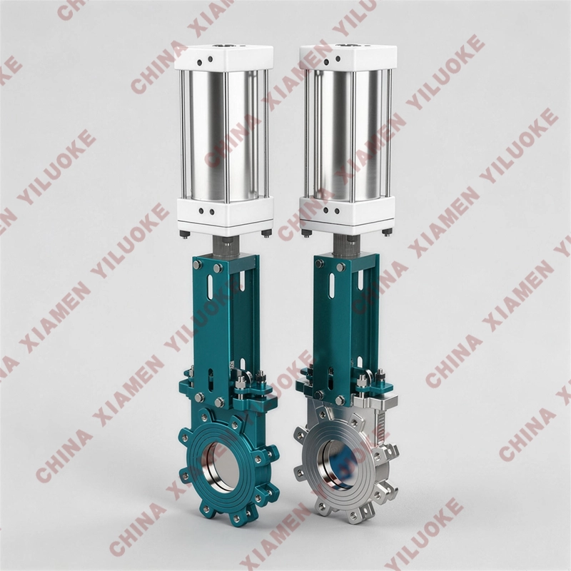
Equipped with accessories such as solenoid valves and proximity switches, the pneumatic knife gate valve can complete two‑position on‑off action control and signal output, as well as automatic continuous action control. Users can select configurations according to actual requirements. Nominal diameter: DN50~DN800, working pressure: 1.0~1.6MPa. Widely used in chemical industry, coal, sugar‑making, sewage treatment, paper‑making and other fields, it is an ideal sealing valve, especially suitable for regulation and throttling on pipelines in paper‑making industry.
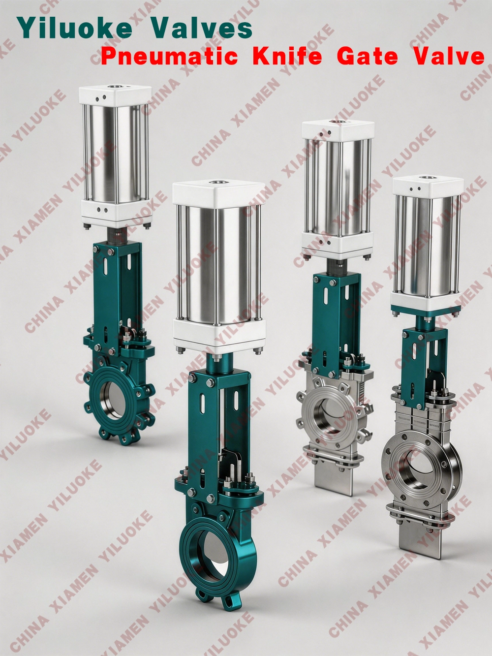
Structural Features
1. Wafer‑type structure with compact size and light weight.
2. Fully open passage prevents medium deposition inside the valve.
3. Newly‑developed U‑shaped sealing ring guarantees excellent valve sealing performance.
4. External sealing of gate plate is realized by elastic sealing strips embedded in valve body, which can be adjusted by screws and pressure plates.
5. Low flow resistance.
6. Convenient for installation and maintenance.
Main Performance Specifications
| Nominal Pressure (MPa) | Shell Test (MPa) | Seal Test (MPa) | Working Temperature | Applicable Media |
| 1.0 | 1.5 | 1.1 | ≤100℃ | Pulp |
| 1.6 | 2.4 | 1.8 | ≤425℃ |
Main Parts Material
| No. | Part Name | C | P | R |
| 1 | Hex Socket Screw | 1Cr18Ni9Ti | 1Cr18Ni9Ti | 1Cr18Ni12Mo2Ti |
| 2 | Valve Cover | WCB | 1Cr18Ni9Ti | ZG1Cr18Ni12Mo2Ti |
| 3 | Gasket | PTFE | PTFE | PTFE |
| 4 | Valve Seat | 1Cr18Ni9Ti or PTFE | 1Cr18Ni9Ti or PTFE | 1Cr18Ni12Mo2Ti or PTFE |
| 5 | Valve Body | WCB | ZG1Cr18Ni9Ti | ZG1Cr18Ni12Mo2Ti |
| 6 | Sealing Packing | NBR or PTFE | NBR or PTFE | NBR or PTFE |
| 7 | Gland | WCB | ZG1Cr18Ni9Ti | ZG1Cr18Ni12Mo2Ti |
| 8 | Gate Plate | 1Cr18Ni9Ti | 1Cr18Ni9Ti | 1Cr18Ni12Mo2Ti |
| 9 | Bracket | WCB | ZG1Cr18Ni9Ti | ZG1Cr18Ni12Mo2Ti |
| 10 | Push‑pull Rod | 45# Steel Chrome‑plated | 45# Steel Chrome‑plated | 45# Steel Chrome‑plated |
| 11 | Pneumatic Actuator |
Technical Parameters
1. Cylinder is a device that converts energy into mechanical linear motion by using compressed air as medium. It is a widely‑used actuator in various pneumatic systems and a basic component for industrial automation.
| Valve DN | Cylinder Specification (Bore × Stroke) | Valve DN | Cylinder Specification (Bore × Stroke) |
| 50 | Φ65×50 | 200 | Φ160×200 |
| 65 | Φ65×65 | 250 | Φ200×250 |
| 80 | Φ80×80 | 300 | Φ200×250 |
| 100 | Φ100×100 | 350 | Φ220×350 |
| 125 | Φ125×125 | 400 | Φ250×400 |
| 150 | Φ125×150 |
2. Technical Parameters
| Cylinder Bore (mm) | Φ40 | Φ50 | Φ63 | Φ80 | Φ100 | Φ125 | Φ160 | Φ200 | Φ250 |
| Theoretical Piston Thrust (N) @0.4MPa | 490 | 760 | 1215 | 1960 | 3077 | 4800 | 7869 | 12308 | 19227 |
| Theoretical Piston Pull Force (N) @0.4MPa | 410 | 680 | 1030 | 1770 | 2675 | 4400 | 7379 | 10035 | 18463 |
Working Medium: Purified compressed air with oil mist
Working Pressure (MPa): 0.15‑1
Ambient Temperature (℃): ‑10‑+80
Relative Humidity: 95%
Piston Speed (mm/s): 50‑500
Durability (KM): 600
3. Cylinder Stroke Selection Range
| Cylinder Bore | Φ40 | Φ50 | Φ63 | Φ80 | Φ100 | Φ125 | Φ160 | Φ200 | Φ250 |
| Stroke Range (mm) | 400 | 500 | 800 | 800 | 1500 | 1500 | 2000 | 2000 | 2500 |
4. Cylinder Operation Notes:
(1) The moving direction of load must be consistent with piston rod movement to avoid piston rod distortion.
(2) Use F‑R‑L combination (filter‑regulator‑lubricator) to improve air quality and extend service life.
(3) Select cylinder with output force higher than actual load to prevent risks caused by insufficient air pressure.
(4) Pay attention to ambient temperature. The applicable temperature for piston ring and sealing parts inside cylinder is generally limited within ‑5℃~+60℃.
(5) For corrosive gas environment, PTFE material shall be adopted for cylinder piston and sealing components.
Air Consumption per 1mm Stroke
| Bore | Air Pressure kg/cm² | ||||||||
| 1 | 2 | 3 | 4 | 5 | 6 | 7 | 8 | 9 | |
| 12 | 0.445 | 0.665 | 0.885 | 1.104 | 1.324 | 1.543 | 1.763 | ‑ | ‑ |
| 16 | 0.792 | 1.182 | 1.573 | 1.963 | 2.352 | 2.743 | 3.133 | ‑ | ‑ |
| 20 | 1.24 | 1.86 | 2.45 | 3.07 | 3.68 | 4.29 | 4.90 | 5.51 | 6.13 |
| 25 | 1.94 | 2.89 | 3.83 | 4.79 | 5.75 | 6.71 | 7.67 | 8.61 | 9.57 |
| 30 | 2.78 | 4.15 | 5.53 | 6.90 | 8.27 | 9.64 | 11.02 | 12.39 | 13.76 |
| 32 | 3.18 | 4.73 | 6.28 | 7.85 | 9.41 | 10.98 | 12.55 | 14.10 | 15.66 |
| 40 | 4.95 | 7.40 | 9.83 | 12.26 | 14.69 | 17.16 | 19.60 | 22.04 | 24.47 |
| 50 | 7.73 | 11.55 | 15.35 | 19.15 | 22.95 | 26.80 | 30.63 | 34.42 | 38.24 |
| 63 | 12.27 | 18.34 | 24.37 | 30.41 | 63.44 | 42.55 | 48.62 | 54.55 | 60.71 |
| 80 | 19.78 | 29.57 | 29.30 | 49.03 | 58.76 | 68.61 | 78.40 | 88.13 | 97.85 |
| 100 | 30.9 | 46.2 | 61.4 | 76.6 | 91.8 | 107.2 | 122.5 | 137.7 | 152.9 |
| 125 | 48.3 | 72.2 | 96.0 | 119.7 | 143.5 | 167.5 | 191.4 | 215.2 | 238.9 |
| 150 | 69.5 | 103.9 | 138.2 | 172.5 | 206.9 | 241.2 | 275.5 | 309.8 | 344.1 |
| 160 | 79.1 | 118.3 | 157.2 | 196.1 | 235.0 | 274.4 | 313.6 | 352.6 | 391.5 |
| 180 | 100.0 | 149.7 | 199.0 | 248.2 | 297.5 | 347.4 | 369.9 | 446.2 | 495.4 |
| 200 | 123.6 | 184.8 | 245.6 | 306.4 | 367.2 | 428.8 | 490.0 | 550.8 | 611.6 |
General Specifications
Size Range: DN50~600mm, NPS 2''‑24'' (Large bore customized on request)
Working Pressure: DN50~DN250: 10Bar, NPS2~NPS10:150Psi; DN300~DN450:7Bar, NPS12~NPS18:90Psi; DN500~DN600:4Bar, NPS20~NPS24:60Psi
Operating Temperature: ‑29~+800℃
Sealing Class: Metal‑seated Class IV, Soft‑seated Class VI. Test standard reference to MSS SP‑81
Valve Body Material: Cast steel, stainless steel, special materials
Trim/Stem Material: Hardened stainless steel, hardened special materials
Seat Material: Hardened stainless steel, EPDM (120°C), Viton(200°C), PTFE(200°C), NBR(90°C)
Face‑to‑Face: MSS SP‑81
Flange Standard: GB/T 9113.1, JB/T 79.1, HG 20592, ASME B16.5, EN1092‑1
Application: Pulp & paper‑making, sewage treatment, food & beverage, chemical industry, energy industry, steel industry, etc.