


Gas Cylinder Pressure Regulator
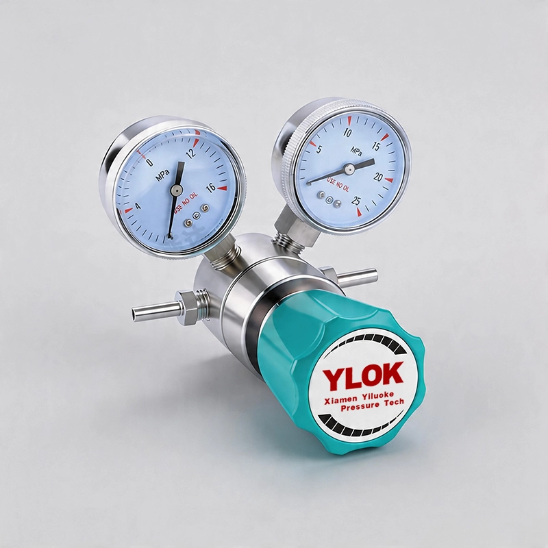
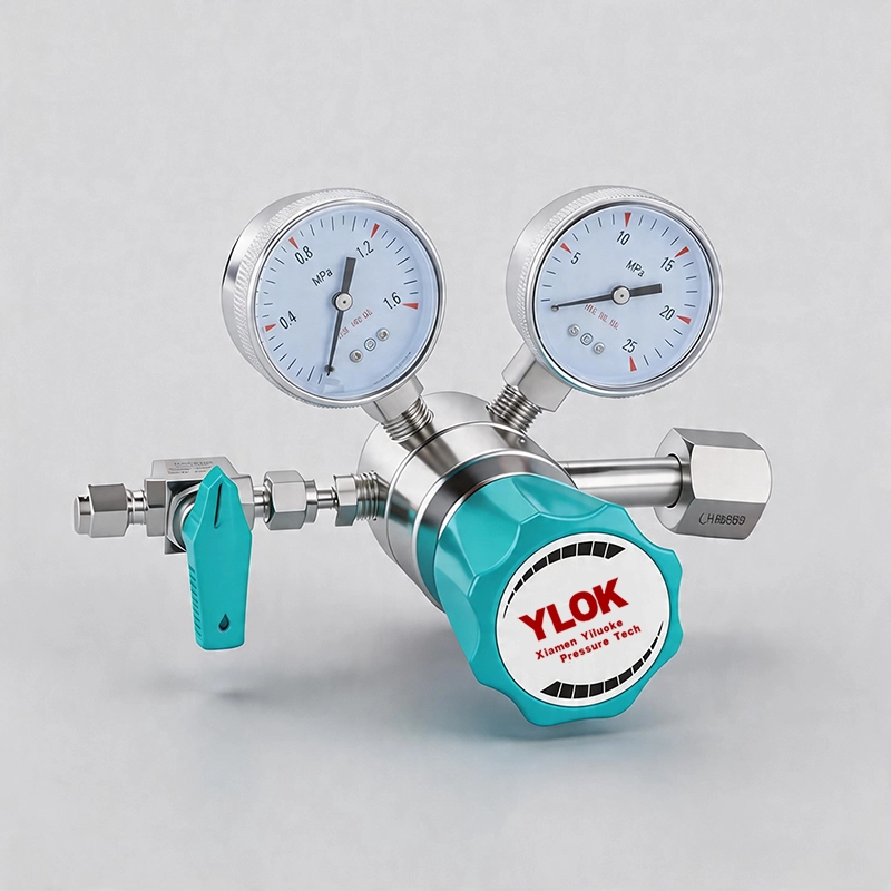
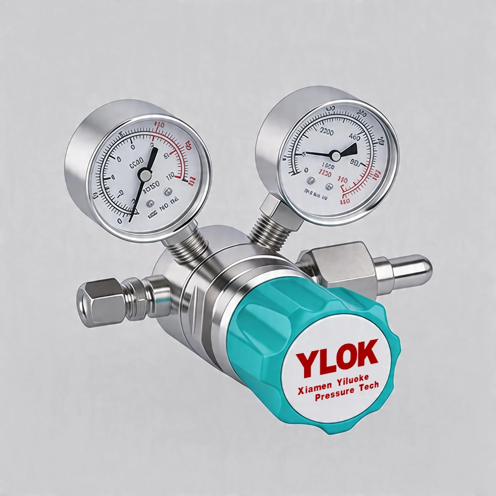
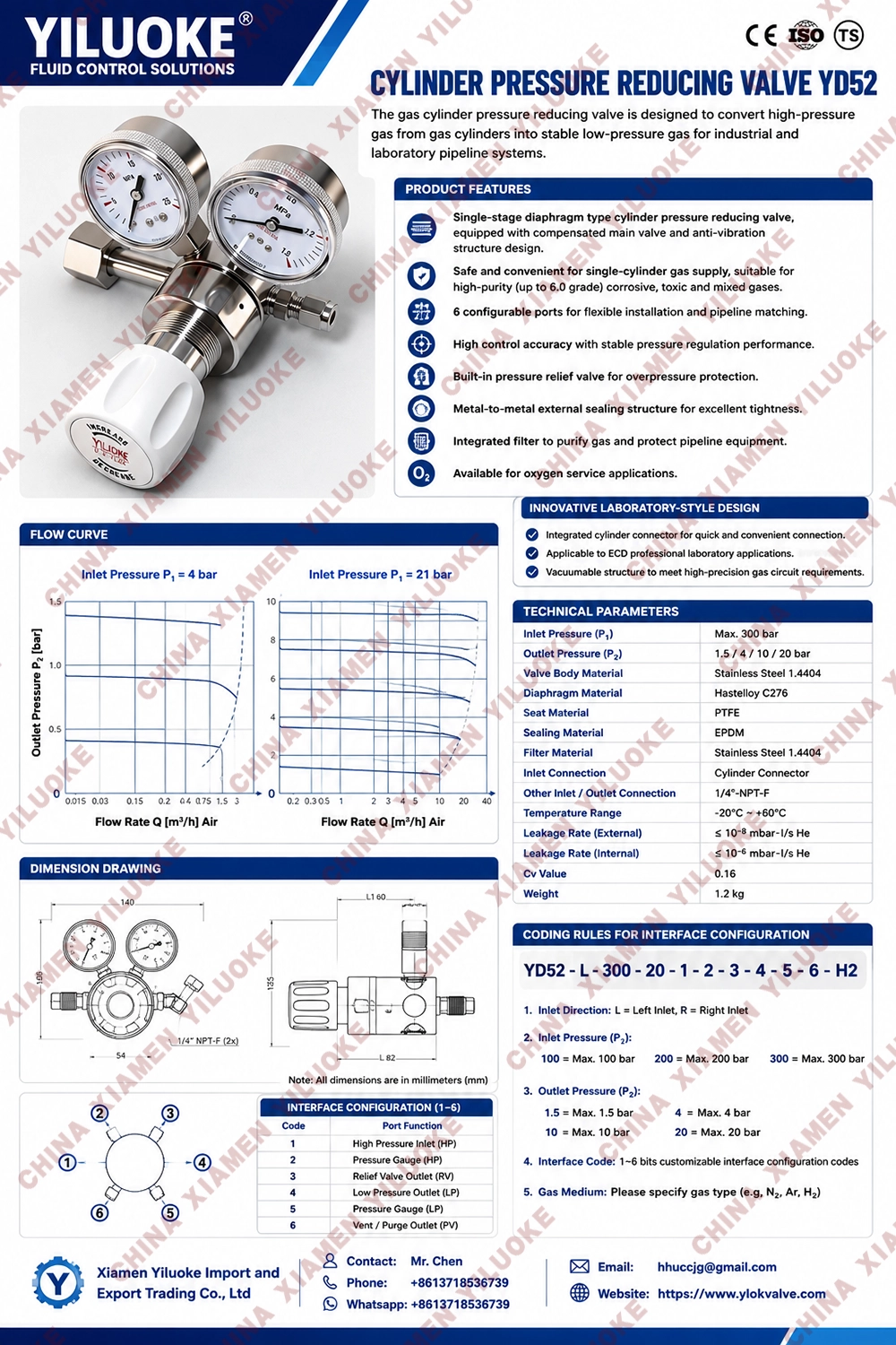
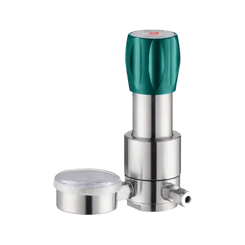
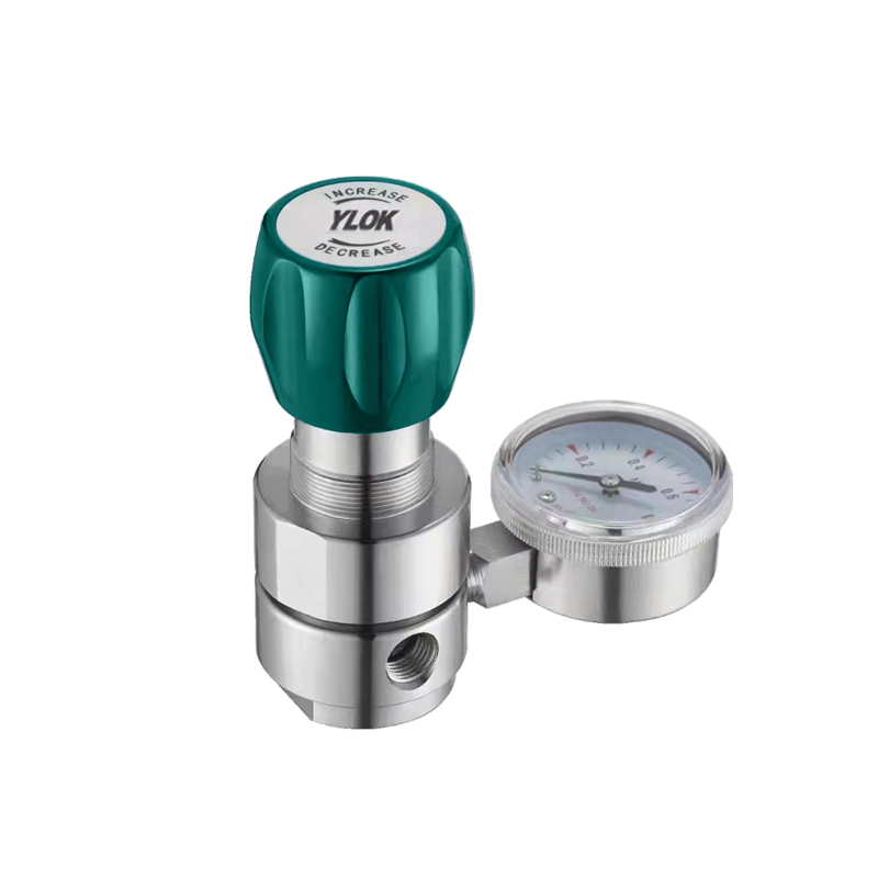
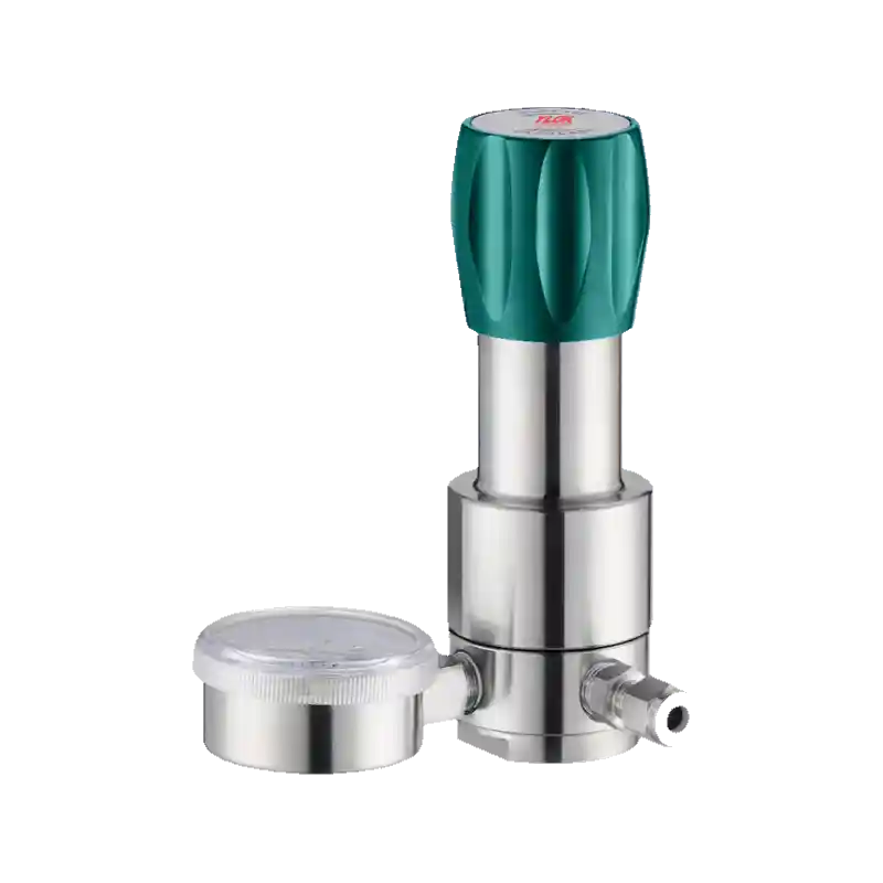
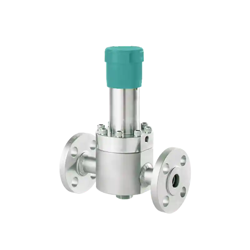
The gas cylinder pressure regulator reduces high‑pressure gas from gas cylinders to low‑pressure gas required for laboratory and working conditions. It adopts diaphragm‑type or piston‑type pressure‑reducing structure for stable output pressure.
Purposes of Gas Cylinder Pressure Regulator
Gases are generally stored in dedicated high‑pressure gas cylinders. During operation, the regulator reduces gas pressure to the required experimental range, and other control valves make fine adjustment to feed gas into the usage system. Since the internal pressure of gas cylinders is relatively high while the pressure required for gas welding, gas cutting and end‑use points is low, a regulator is required to lower high‑pressure gas stored in cylinders to low‑pressure gas and maintain stable working pressure all the time. The gas cylinder pressure regulator is a regulating device that reduces high‑pressure gas to low‑pressure gas and keeps stable output pressure and flow rate.
Application Fields
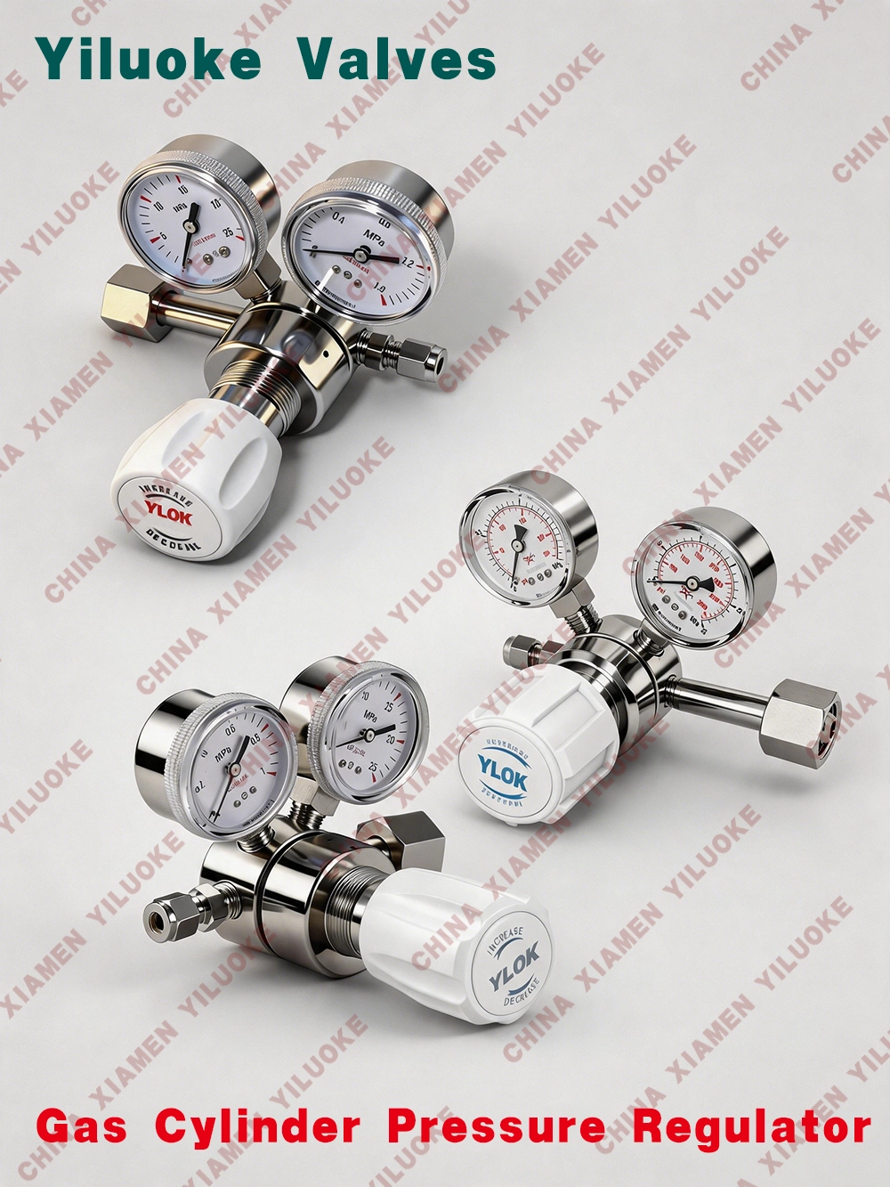
It is mainly used for outlet pressure reduction of nitrogen, oxygen, helium, hydrogen, argon and acetylene gas cylinders in petroleum‑chemical industry, laboratory equipment, chemical fiber, lighting electric appliances, heat treatment, metallurgy, glass, food, pharmaceutical, electronics, national defense aerospace and aviation industries.
Structural Features
Compact structure with stable output pressure.
Metal sealing is adopted between diaphragm and body.
316L stainless steel material, suitable for corrosive, non‑corrosive and toxic gases.
Metal diaphragm guarantees output stability and long service life.
Panel mounting is optional.
Technical Parameters
| Part Name | Material |
| Body | 316L, Brass |
| Top Cover | 316L, Brass |
| Diaphragm | 316L |
| Filter Screen | 316L (10μm) |
| Seat | PCTFE, PTFE, Vespel |
| Spring | 316L |
| Valve Core Stem | 316L |
Application Scope: Semiconductor manufacturing process, laboratory, gas phase analysis, test instruments, petrochemical industry, power plant equipment
| Max. Inlet Pressure | 15MPa, 20MPa, 25MPa, 40MPa; 6000PSI, 3000PSI, 500PSI |
| Output Pressure | 0‑0.1MPa, 0‑1MPa, 0‑5MPa, 0‑10MPa, 0‑15MPa, 0‑35MPa; 0~25, 0~100, 0~300, 0‑3000, 0‑4500PSI |
| Inlet Connection | G1/4, G1/2, G5/8, G1 |
| Outlet Connection | 1/4", matched with various adapters |
| Test Pressure | 1.5 times of maximum inlet pressure |
| Applicable Temperature | -40°F to +165°F (-40℃ to +74℃) |
Installation Instructions for Gas Cylinder Pressure Regulator
1. Securely connect the thread of regulator inlet/outlet joints with cylinder valve thread or high‑low pressure side pipeline by spanner to prevent gas leakage. Do not rotate the regulator body; clamp the body and tighten the nut.
2. During installation, ensure no loosening at joints between regulator inlet/outlet and regulator body, otherwise gas leakage may occur and bring major safety hazards.
3. Thoroughly remove oil stains, water and dust at connecting positions of cylinder, pipeline system and regulator. Once impurities enter the gas regulator, they may contaminate gas, block gas channels or cause other troubles.
4. If thread deformation occurs on pipelines and fails to fit with gas regulator smoothly, do not force connection. Otherwise, threads of pipeline system and gas regulator may be damaged and result in serious accidents.
Operation Instructions for Gas Cylinder Pressure Regulator
1. Before gas flows into the regulator, confirm that pipeline system (including regulator) has been purged or vacuumized as required.
2. Before gas flows into the regulator, confirm that the adjusting knob of regulator is fully loosened (rotate counter‑clockwise). Otherwise, instantaneous pressure at initial gas supply may damage the diaphragm, cause regulator failure and even endanger personal safety.
3. Slowly open the gas supply valve on regulator inlet side, and inspect all regulator joints for leakage with soapy water or special detector.
Note: Do not face or back towards the regulator when opening the gas supply valve.
4. Rotate the regulator adjusting knob clockwise to adjust pressure (or flow rate) to required scale position, and check all joints for leakage with soapy water or special detector.
Note: If abnormal mechanical vibration, noise, jamming or abnormal pressure rise occurs during gas supply, the regulator is faulty. Stop using immediately.
Common Gas Cylinder Connector Model Comparison Table
| GAS TYPE | Molecular Formula | Gas Category | National Standard | CGA | UHP CGA | DIN | JIS |
| High Purity Gas | High Purity Gas | W21.8‑14RHF | 180 | 350 | |||
| Acetylene | C2H2 | Acetylene | Roller gland | 200/300/510 | N/A | N/A | N/A |
| Air | Air | Air | G5/8"-RHF | 346/590 | N/A | N/A | N/A |
| Ammonia | NH3 | Ammonia | G1/2"-RHF | 705 | 720 | DIN6 | 22‑R |
| Argon | Ar | Argon | G5/8"-RHF | 580 | 718 | DIN6 | 22‑4O/23‑R |
| Arsine | AsH3 | Arsine | N/A | 350 | 632 | N/A | 22‑l |
| Boron Trichloride | BCl3 | Boron Trichloride | G3/4"-RHF/W21.8‑14RHF | 660 | 634 | DIN8 | N/A |
| Boron Trifluoride | BF3 | Boron Trifluoride | G3/4"-RHF/W21.8‑14RHF | 330 | 642 | DIN8 | 22‑l |
| Butane | C4H8 | Butane | M22*1.5‑LHM | 510 | N/A | N/A | N/A |
| Carbon Dioxide | CO2 | Carbon Dioxide | G5/8"-RHF | 320 | 716 | DIN6 | N/A |
| Carbon Monoxide | CO | Carbon Monoxide | W21.8‑14LHF | 350 | 724 | DIN5 | 22‑l |
| Cyclopropane | C3H6 | Cyclopropane | M22*1.5‑LHM | 510 | N/A | N/A | N/A |
| Diborane | B2H6 | Diborane | N/A | 350 | 632 | N/A | 22‑l |
| Dichlorosilane | CH3SiHCl2 | Dichlorosilane | N/A | 678 | 636 | DIN5 | N/A |
| Diethylzinc | (CH3CH2)2Zn | Diethylzinc | N/A | 510 | 726 | N/A | N/A |
| Ethane | C2H6 | Ethane | M22*1.5‑LHM | 350 | N/A | N/A | N/A |
| Ethyl Chloride | C2H5Cl | Ethyl Chloride | G3/4"-RHF | 510 | N/A | N/A | N/A |
| Ethylene | C2H4 | Ethylene | M22*1.5‑LHM | 350 | N/A | N/A | N/A |
| Ethylene Oxide | CH2CH2O | Ethylene Oxide | G5/8"-RHF/G3/4"-RHF | 510 | N/A | N/A | N/A |
| Germane | GeH4 | Germane | N/A | 350or660 | 632 | N/A | N/A |
| Halocarbon11(116) | R11(R116) | G3/4"-RHF | 660 | 716 | N/A | N/A | |
| Halocarbon12 | R12(R13,R23,R115) | G3/4"-RHF | 660 | 716 | DIN6 | N/A | |
| Halocarbon14 | R14 | G3/4"-RHF | 320/580 | 716 | DIN6 | N/A | |
| Helium | He | Helium | G5/8"-RHF | 580 | 718 | DIN6 | 22‑R/23‑R |
| Hydrogen | H2 | Hydrogen | W21.8‑14LHF | 350 | 724 | DIN1 | 22‑L |
| Hydrogen Chloride | HCl | Hydrogen Chloride | G3/4"-RHF | 330 | 634 | DIN8 | 26‑R |
| Hydrogen Fluoride | HF | Hydrogen Fluoride | G3/4"-RHF/W21.8‑14RHF | 660/670 | 638 | N/A | 26‑R |
| Hydrogen Sulfide | H2S | Hydrogen Sulfide | G3/4"-RHF/W21.8‑14RHF | 330 | 722 | DIN5 | N/A |
| Iso‑Butane | I‑C4H8 | Iso‑Butane | M22*1.5‑LHM | 510 | N/A | N/A | N/A |
| Krypton | Kr | Krypton | G5/8"-RHF | 580 | 718 | DIN6 | 22‑R/23‑R |
| Methane | CH4 | Methane | W21.8‑14LHF | 350 | N/A | N/A | N/A |
| Methyl Chloride | CH3Cl | Methyl Chloride | G3/4"-RHF/W21.8‑14RHF | 660 | N/A | N/A | N/A |
| Natural Gas | Natural Gas | W21.8‑14LHF/M22*1.5‑LHM | 350 | N/A | N/A | N/A | |
| Neon | Ne | Neon | G5/8"-RHF | 580 | 718 | DIN6 | 22‑R/23‑R |
| Nitric Oxide | NO | Nitric Oxide | G3/4"-RHF/W21.8‑14RHF | 660 | N/A | N/A | N/A |
| Nitrogen | N2 | Nitrogen | G5/8"-RHF | 580 | 718 | DIN10 | 22‑R/23‑R |
| Nitrogen Trifluoride | NCl3 | Nitrogen Trifluoride | G3/4"-RHF/W21.8‑14RHF | 330/670 | 640 | DIN8 | N/A |
| Nitrous Oxide | N2O | Nitrous Oxide | G5/8"-RHF | 326/660 | 712 | DIN8 | N/A |
| Oxygen | O2 | Oxygen | G5/8"-RHF | 540 | 714 | DIN9 | 22‑R/23‑R |
| Phosphine | PH3 | Phosphine | W21.8‑14LHF | 350 | 632 | DIN1 | N/A |
| Propane | C3H8 | Propane | M22*1.5‑LHM | 510 | N/A | N/A | N/A |
| Silane | SiH4 | Silane | G3/4"-RHF/W21.8‑14RHF | 350 | 632 | N/A | N/A |
| Silicon Tetrachloride | SiCl4 | Silicon Tetrachloride | G3/4"-RHF/W21.8‑14RHF | 330 | 636 | N/A | N/A |
| Silicon Tetrafluoride | SiF4 | Silicon Tetrafluoride | G3/4"-RHF/W21.8‑14RHF | 330 | 642 | N/A | 22‑L |
| Sulfur Hexafluoride | SF6 | Sulfur Hexafluoride | G5/8"-RHF | 590 | 716 | DIN6 | 26‑R |
| Tungsten Hexafluoride | WF6 | Tungsten Hexafluoride | N/A | 670 | 638 | DIN8 | N/A |
| Xenon | Xe | Xenon | G5/8"-RHF | 580 | 718 | DIN6 | 22‑R |
Note 1: 40L / 10L stainless steel cylinder valve standard: G3/4"-RHF
Note 2: Cylinder valve standard for cylinders below 10L: W21.8‑14RHF
Leave Your Message
Products categories
-
High Pressure Regulator
-
Ammonia Gas Pressure Regulator
-
Micro-Pressure Back-Pressure Regulators
-
Stainless Steel Back-Pressure Regulators
-
Low-Pressure Back-Pressure Regulators
-
Hydrogen Back-Pressure Regulators
-
Gas Back-Pressure Regulators
-
Liquid backpressure regulators
-
High-Flow Backpressure Valves