


Flanged Butterfly Valves
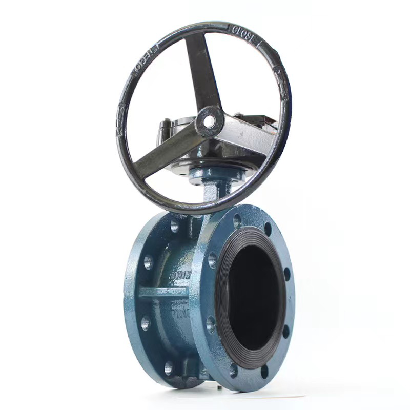
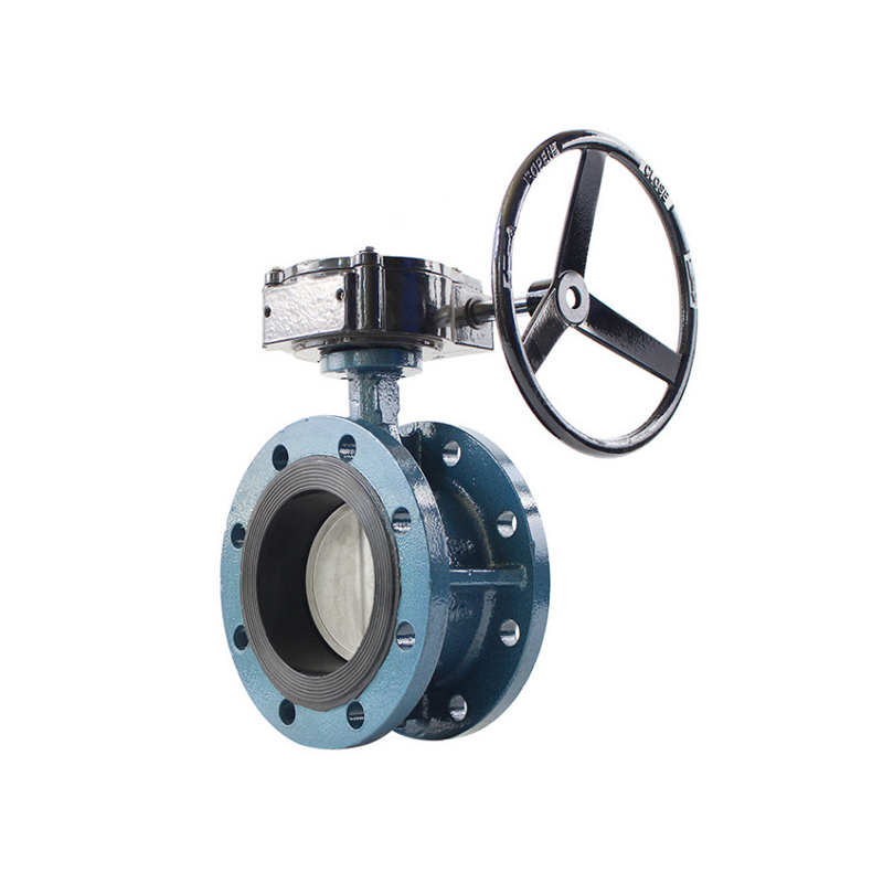
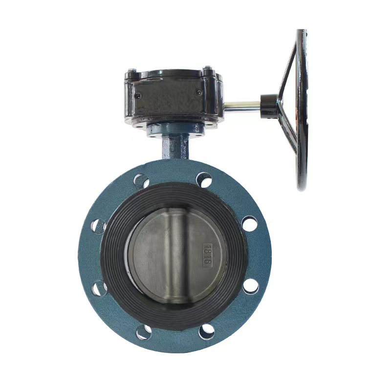
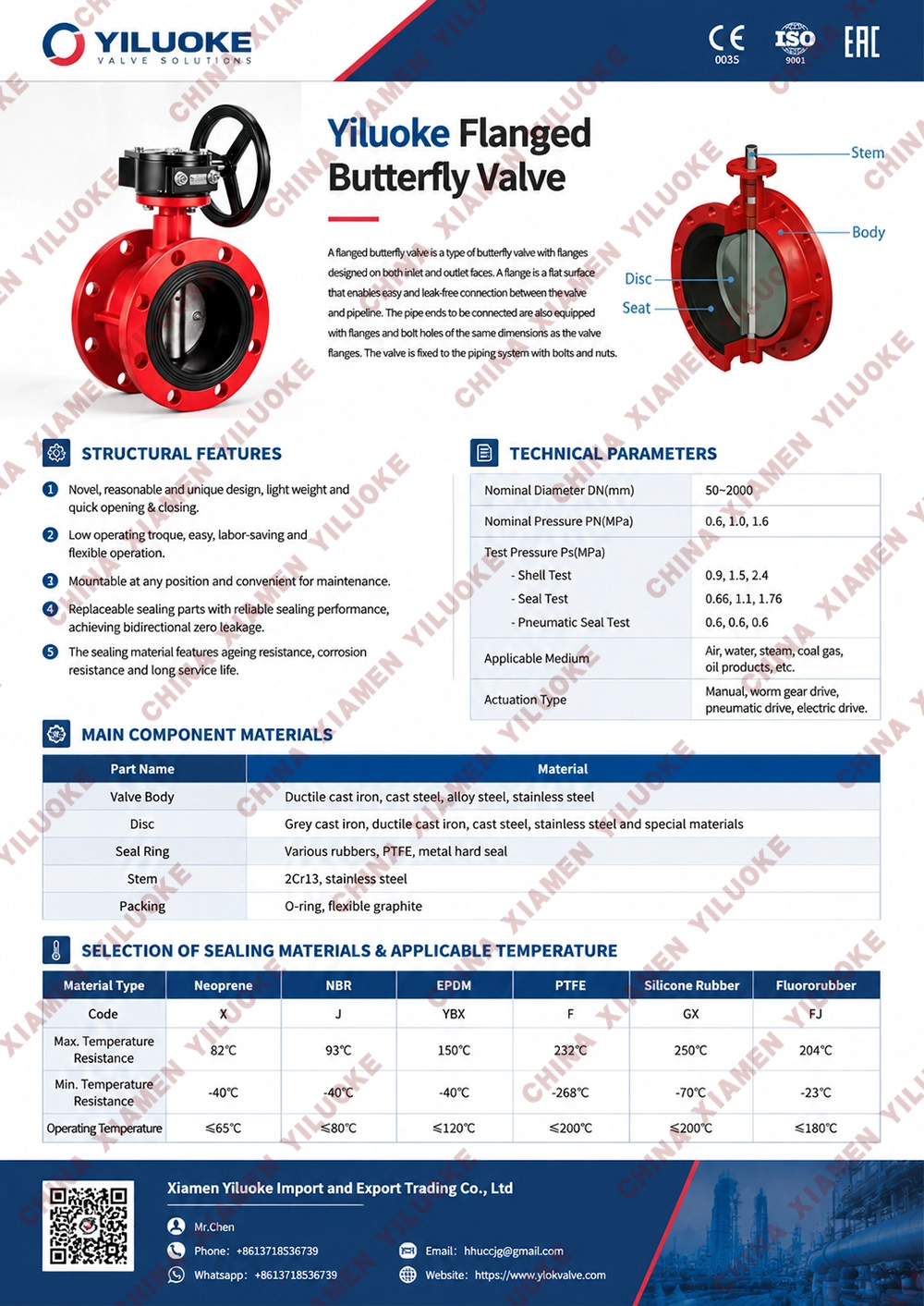
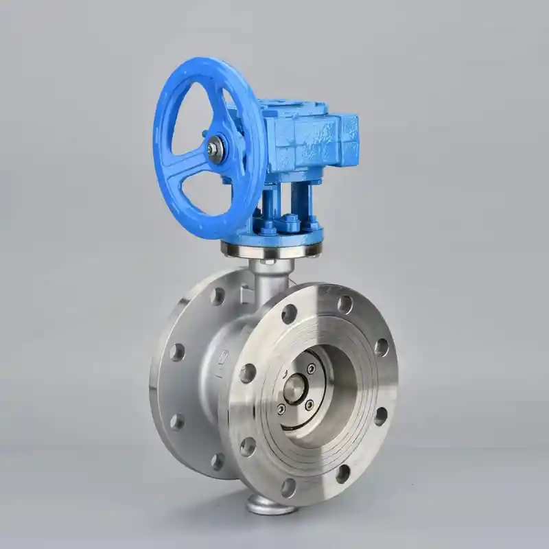
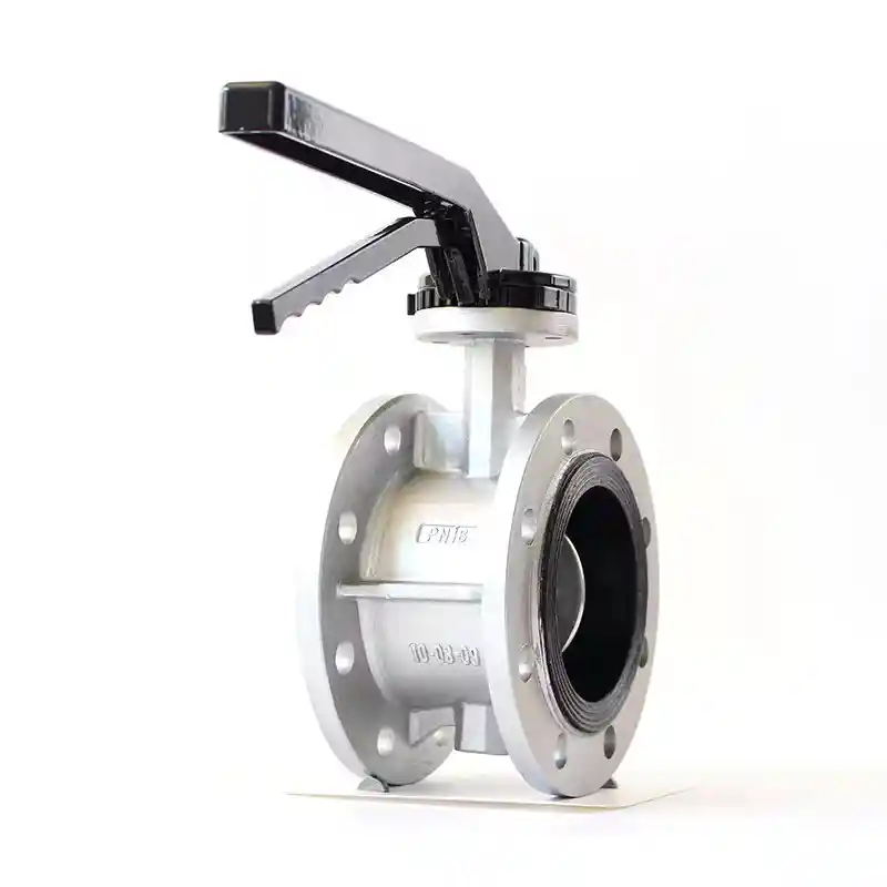
Flanged butterfly valve is a conventional butterfly valve for pipeline selection. It features simple and compact structure, low flow resistance coefficient, nearly linear flow characteristic, no debris accumulation, light weight, convenient installation and low operating torque. This valve can be used for medium shut-off as well as flow regulation. It combines partial advantages of eccentric flanged butterfly valves and wafer butterfly valves, filling the gap between the two types. Flanged butterfly valves are mainly applied in water supply & drainage, sewage treatment, heating, gas supply, chemical industry, power plants, municipal engineering and water plants for pipelines conveying water, oil and air to cut off fluid or regulate medium flow.
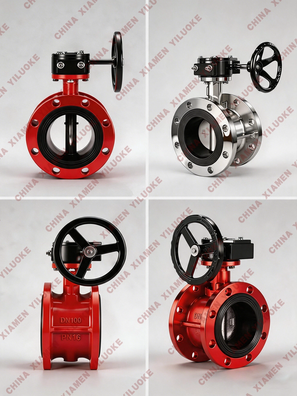
Structural Design Features
1. Compact and lightweight, easy to disassemble, repair and install at any position.
2. Simple and compact structure with low operating torque; 90-degree rotation enables rapid opening.
3. Nearly linear flow characteristic with excellent regulating performance.
4. Pinless connection between disc and stem eliminates potential internal leakage points.
5. Spherical outer surface of the disc improves sealing performance and extends service life.
6. Back-seated soft-seal design allows replaceable sealing elements and achieves reliable bidirectional sealing.
7. Disc surface can be coated with nylon, PTFE and other materials as required by customers.
8. Optional actuation modes: manual, electric and pneumatic.
Technical Parameters
| Item | Specification | Item | Specification |
|---|---|---|---|
| Brand | Xiamen Yiluoke | Product Name | Worm Gear Flanged Butterfly Valve |
| Model | D341X/D341F | Body Material | Ductile Iron QT450 / WCB Carbon Steel / CF8 / CF8M / CF3M Stainless Steel |
| Connection Type | Flanged | Nominal Diameter | DN40~DN1200 |
| Actuation | Manual | Applicable Media | Water, gas, oil |
| Temperature Range | -20℃~120℃ | Nominal Pressure | 1.0MPa~1.6MPa |
| Surface Treatment | Epoxy Coating | Disc Material | Ductile Iron / 304 / 316 Stainless Steel / Aluminum Bronze |
| Stem Material | 304 / 316 / 416 Stainless Steel | Seat Material | NBR / EPDM / FPM |
| Design & Manufacturing Standards | GB/T 12238-2008; ISO 10631-1991; API598 | Face-to-Face Dimension Standard | GB/T 12221-2005; ISO 5752-1988 |
| Valve Test Standard | GB/T 13927-2008; ISO 5208-1987 | Manufacturing Standards | GB, JB, HG, ANSI, API, JIS, DIN and customized standards |
Overall Dimensions
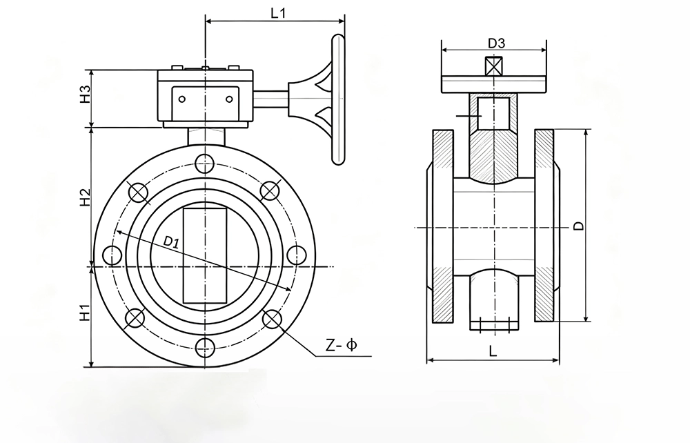
| DN | L | L1 | PN10 | PN16 | 150LB | 10K | Flange Code | D3 | H1 | H2 | H3 | ||||||||
|---|---|---|---|---|---|---|---|---|---|---|---|---|---|---|---|---|---|---|---|
| D | D1 | Z-d | D | D1 | Z-d | D | D1 | Z-d | D | D1 | Z-d | ||||||||
| 50 | 108 | 160 | 165 | 125 | 4-19 | 165 | 125 | 4-23 | 150 | 120.6 | 4-19 | 155 | 120 | 4-19 | F05 | 73 | 125 | 60 | |
| 65 | 112 | 160 | 185 | 145 | 4-19 | 185 | 145 | 4-23 | 180 | 139.7 | 4-19 | 175 | 140 | 4-19 | F05 | 82 | 136 | 60 | |
| 80 | 114 | 160 | 200 | 160 | 8-19 | 200 | 160 | 8-20 | 190 | 152.4 | 4-19 | 185 | 150 | 8-19 | F05 | 91 | 142 | 60 | |
| 100 | 127 | 160 | 220 | 180 | 8-19 | 220 | 180 | 4-23 | 230 | 190.5 | 8-19 | 210 | 175 | 8-19 | F07 | 104 | 163 | 60 | |
| 125 | 140 | 160 | 250 | 210 | 8-19 | 250 | 210 | 4-23 | 255 | 215.9 | 8-22 | 250 | 210 | 8-23 | F07 | 127 | 176 | 60 | |
| 150 | 140 | 160 | 285 | 240 | 8-23 | 285 | 240 | 4-25 | 280 | 241.3 | 8-22 | 280 | 240 | 8-23 | F07 | 138 | 197 | 60 | |
| 200 | 152 | 210 | 340 | 295 | 8-23 | 340 | 295 | 4-25 | 345 | 298.5 | 8-22 | 330 | 290 | 12-23 | F10 | 170 | 230 | 72 | |
| 250 | 165 | 210 | 395 | 350 | 12-23 | 405 | 355 | 4-28 | 405 | 362 | 12-25 | 400 | 355 | 12-25 | F10 | 204 | 261 | 72 | |
| 300 | 178 | 210 | 445 | 400 | 12-23 | 460 | 410 | 4-28 | 485 | 432 | 12-25 | 445 | 400 | 16-25 | F10/12 | 241 | 294 | 75 | |
| 350 | 190 | 210 | 505 | 460 | 16-23 | 520 | 470 | 4-30 | 535 | 476 | 12-29 | 490 | 445 | 16-25 | F10/12 | 263 | 335 | 75 | |
| 400 | 216 | 320 | 565 | 515 | 16-28 | 580 | 525 | 4-30 | 600 | 540 | 16-29 | 560 | 510 | 16-27 | F14/16 | 309 | 400 | 126 | |
| 450 | 222 | 320 | 615 | 565 | 20-28 | 715 | 650 | 4-33 | 700 | 635 | 20-32 | 675 | 620 | 20-27 | F14/16 | 328 | 420 | 126 | |
| 500 | 229 | 320 | 670 | 620 | 20-28 | 715 | 650 | 4-33 | 700 | 635 | 20-32 | 675 | 620 | 20-27 | F14/16 | 361 | 480 | 126 | |
| 600 | 267 | 340 | 780 | 725 | 20-31 | 840 | 770 | 4-36 | 815 | 749.5 | 20-35 | 795 | 730 | 24-32 | F16 | 459 | 560 | 127 | |
| 700 | 292 | 380 | 895 | 840 | 24-31 | 910 | 840 | 24-36 | - | 864 | 28-35 | 905 | 840 | 24-33 | F25 | 520 | 624 | 167 | |
| 800 | 318 | 380 | 1015 | 950 | 24-34 | 1025 | 950 | 24-39 | - | 978 | 28-41 | 1020 | 950 | 28-33 | F25 | 590 | 680 | 167 | |
| 900 | 330 | 400 | 1115 | 1050 | 28-34 | 1125 | 1050 | 28-39 | - | 1089 | 32-41 | 1120 | 1050 | 28-33 | F25 | 656 | 720 | 193 | |
| 1000 | 410 | 400 | 1230 | 1160 | 28-37 | 1255 | 1170 | 28-42 | - | 1200 | 36-41 | 1235 | 1160 | 28-39 | F25 | 720 | 800 | 193 | |
| 1200 | 470 | 450 | 1455 | 1380 | 32-40 | 1485 | 1390 | 28-49 | - | 1422 | 44-41 | 1465 | 1380 | 32-39 | F30 | 844 | 941 | - | |
Applications
Flanged butterfly valve features simple, compact structure, reliable sealing performance and long service life. It is equipped with aluminum handle and suitable for on-off control of low-pressure pipeline media. Widely used in water supply & drainage pipelines of water plants, power plants, paper mills and chemical factories, especially for shut-off service on tap water pipelines.
Installation, Operation & Maintenance Instructions
1. All valves have passed inspection and actuator commissioning in accordance with GB/T13927-92 and JB/T9092-99 before delivery. Do not arbitrarily adjust fasteners and positioning devices to guarantee performance.
2. Pre-installation Checklist
2-1. The arrow marked on valve body indicates flow direction; do not install reversely.
2-2. Verify pipeline flange dimensions match valve flanges. Tighten nuts evenly and place gaskets symmetrically.
2-3. Confirm working conditions match valve pressure, temperature and corrosion resistance ratings.
2-4. Clean dirt inside valve bore and disc. Avoid scratching sealing surfaces during cleaning.
2-5. Check all components for tightness and integrity.
2-6. This valve is single-direction sealed. Verify opening/closing position and check for jamming.
3. The valve can be mounted at any position, available for shut-off and flow regulation.
4. For manual operation: clockwise for closing, counter-clockwise for opening. Refer to position indicator scale during operation.
5. When faults occur during operation, identify and resolve issues promptly. Do not strike or force open/close the valve.
6. Keep the valve fully open when conducting pipeline hydrostatic test after installation.
7. On-site valve testing shall comply with GB/T13927-92 or JB/T9092-99.
8. Regularly add lubricant to the actuator if the valve operates frequently.
9. Please refer to manufacturer manuals for electric, pneumatic and hydraulic actuators.
10. Avoid collision during transportation to prevent damage to sealing surfaces and actuators.
Leave Your Message
Products categories
-
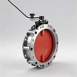
Powder Butterfly Valve
-
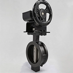
Double Eccentric High‑Performance Butterfly Valve
-
UPVC Plastic Butterfly Valve
-
Aluminum Alloy Anti‑Condensation Butterfly Valve
-
Stainless Steel Metal Hard Seal Butterfly Valves
-
Rubber Lined Butterfly Valves
-
Stainless Steel Flanged Butterfly Valves
-
PTFE-Lined Butterfly Valves
-
Wafer Type Butterfly Valves