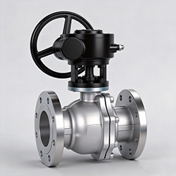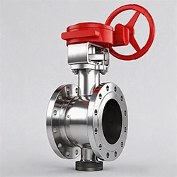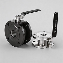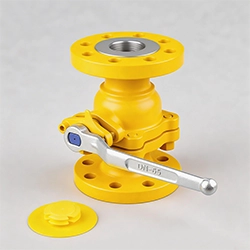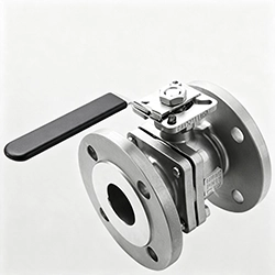


3-Way Ball Valves
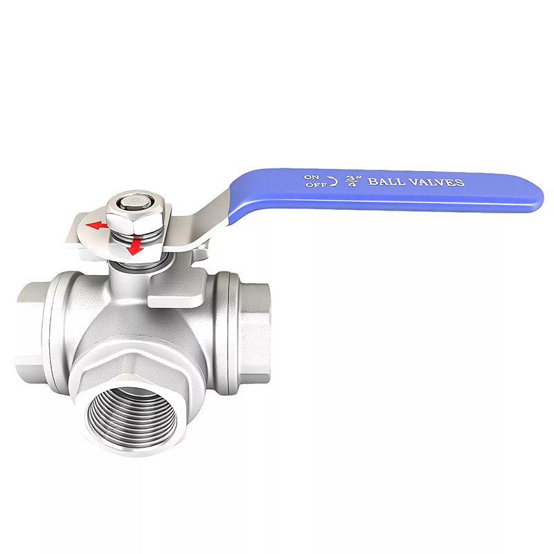
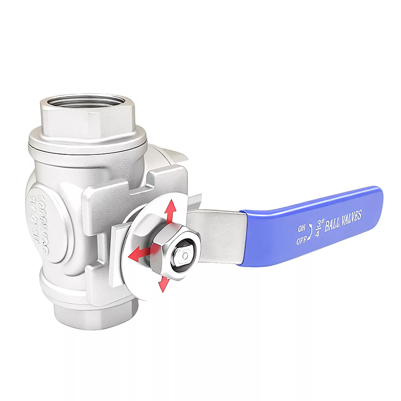
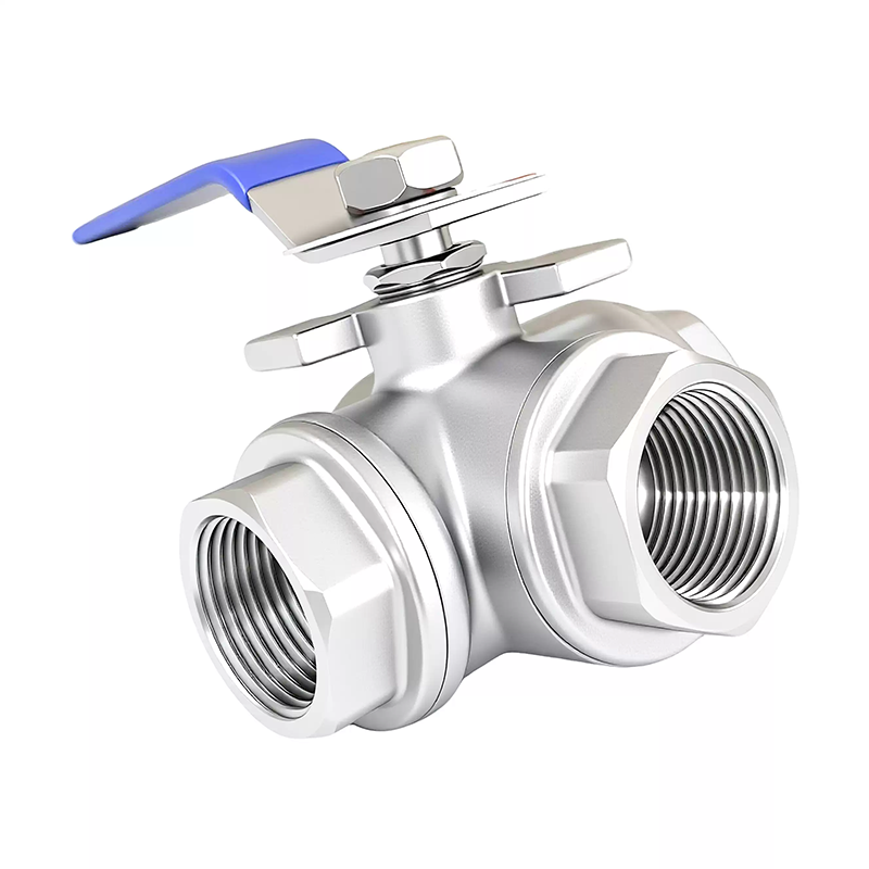
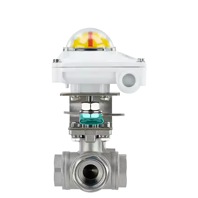
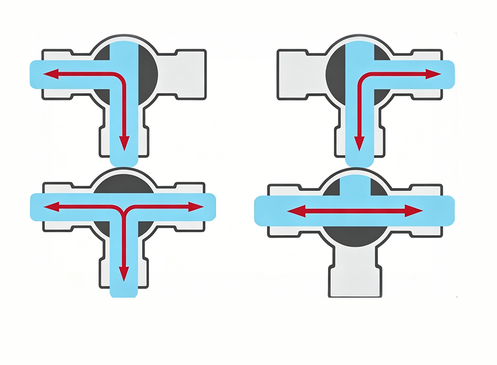
3-way ball valves are mainly used in pipelines for cutting off, distributing and changing the flow direction of media. There are T-type and L-type 3-way ball valves. The T-type can connect and cut off three orthogonal pipelines to play the role of flow splitting and confluence. The L-type 3-way ball valve can only connect two orthogonal pipelines and cannot keep the third pipeline connected at the same time, so it only plays the role of distribution.
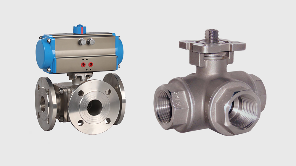
Features of 3-Way Ball Valves
Two-seat sealed 3-way ball valve: The L-type flow mode (sometimes called a 90-degree ball) is most commonly used to allow flow from a common inlet to one of two different outlets. That is why L-type flow 3-way ball valves are usually referred to as diverter valves.
Four-seat sealed 3-way ball valve: The T-type flow ball (sometimes also called a 180-degree ball) is widely used to take two inlet flows and merge them to flow out through a common outlet. Depending on process requirements, it can also be reversed. That is to say, split the flow from a common port into two outgoing flows, each leaving the valve through a different valve port. T-type flow valves are not limited to splitting or merging. They can also work like L-type flow valves and divert flow from one outlet to another. In an important way, T-type flow ball valves are quite different from L-type flow ball valves. A typical T-type flow valve cannot provide shut-off control. They can restrict flow to any two of the three valve ports, or allow flow through all three valve ports simultaneously. That is why T-type flow ball valves are sometimes called mixing valves.
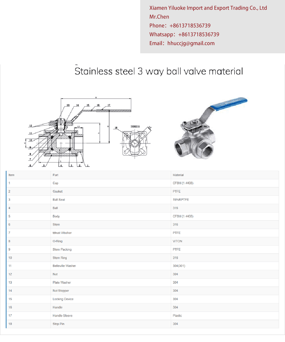
Main Parts and Materials
Accessory Name | GB Standard Material | ASTM Standard Material |
|---|---|---|
Body & Bonnet | WCB | A216-WCB |
Seat | PTFE, PPL (Polyphenylene Sulfide) | PTFE, PPL (Polyphenylene Sulfide) |
Ball | 1Cr18Ni9Ti | SS 304 |
Stem | 2Cr13 | A276-410 |
Stud Bolt | 35CrMoA | A193-B7 |
Main Performance Specification
Nominal Pressure | Shell Test Pressure (MPa) | High-pressure Liquid Sealing Test Pressure (MPa) | Low-pressure Gas Sealing Test Pressure (MPa) |
|---|---|---|---|
PN 1.6 MPa | 2.4 | 1.76 | 0.6 |
PN 2.5 MPa | 3.75 | 2.75 | - |
PN 4.0 MPa | 6.0 | 4.4 | - |
CLASS 150 | 3.0 | 2.2 | - |
Applicable Specification
Item | Parameter / Specification |
|---|---|
Applicable Medium | Non-corrosive medium such as water, oil, gas, etc., and acid-base corrosive medium |
Applicable Temperature | -28℃ ~ +280℃ |
Connecting Flange | JB79-94, GB9113, HG20592-09, ANSI B16.5 |
Test & Inspection | JB/T9092-99, API 598 |
Other Manufacturing Standards | In accordance with the factory's internal standards |
Remarks
3-way ball valves generally adopt a two-seat structure, suitable for two working conditions as shown in Flow Direction Diagram A. The two-seat L-port structure (i.e., Model Q44) shall be selected for this scenario. For working conditions ① and ④ in Flow Direction Diagram B, the two-seat T-port structure (i.e., Model Q45) can also be selected. For working conditions ② and ③ in Flow Direction Diagram B, the four-seat T-port structure (i.e., Model Q45) must be selected. The four-seat structure can also be selected for other working conditions, but the valve seat structure shall be specified in the order contract. If there are other requirements for the valve, please refer to the product catalog and fill in the corresponding requirement codes.
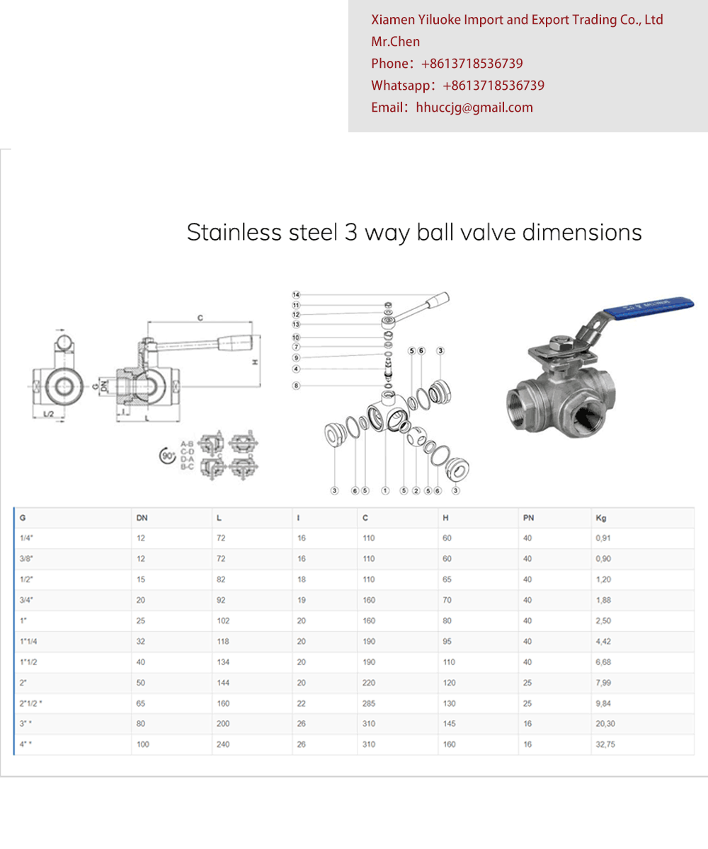
Technical Parameters
Product Name | 3-Way Ball Valve |
Nominal Diameter | DN15~DN300 |
Structure Type | Spherical |
Nominal Pressure | 1.6MPa~6.4MPa |
Connection Method | Flanged, Internal Threaded |
Applicable Temperature | ≤350℃ |
Drive Method | Manual, Electric Actuated, Pneumatic |
Valve Body Material | Cast Steel, Stainless Steel |
Manufacturing Standards | National Standard GB, German Standard DIN, American Standard API, ANSI |
Applicable Media | Water, Oil, Gas, Liquid |
FAQ
1:Differences Between L-port 3-Way Ball Valve and T-port 3-Way Ball Valve
L-port 3-Way Ball Valve The L-port flow pattern (also known as 90° ball) is mostly used to divert flow from one common inlet to either of two separate outlets, hence it is generally referred to as a diverting valve. Schematic diagram for flow direction of L-port 3-way ball valve
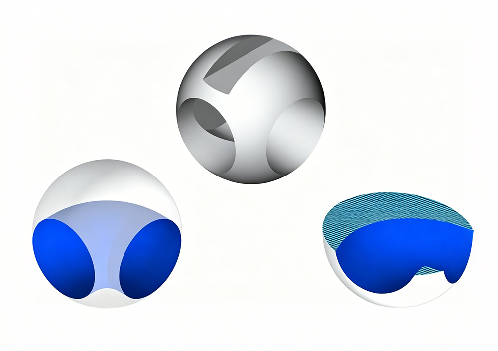
T-port 3-Way Ball Valve The T-port ball (also called 180° ball) is widely applied to combine two incoming medium streams and discharge them through one shared outlet, and the flow direction can be reversed per process requirements. That is, it can split fluid from one common port into two separate outlet streams through different valve ports. T-port valves are not limited to flow splitting or converging. They can also switch fluid flow between two outlets just like L-port valves. The core difference between T-port and L-port ball valves lies in shut-off performance: standard T-port valves cannot fully cut off flow. They can conduct fluid between any two of the three ports, or allow medium to pass through all three ports simultaneously, so T-port ball valves are also named mixing valves.
Related Products:Electric Actuated High-Pressure 3-Way Ball Valves,Pneumatic 3-way Ball Valves