


Self-Operated Micro Pressure Control Valve
Product Overview
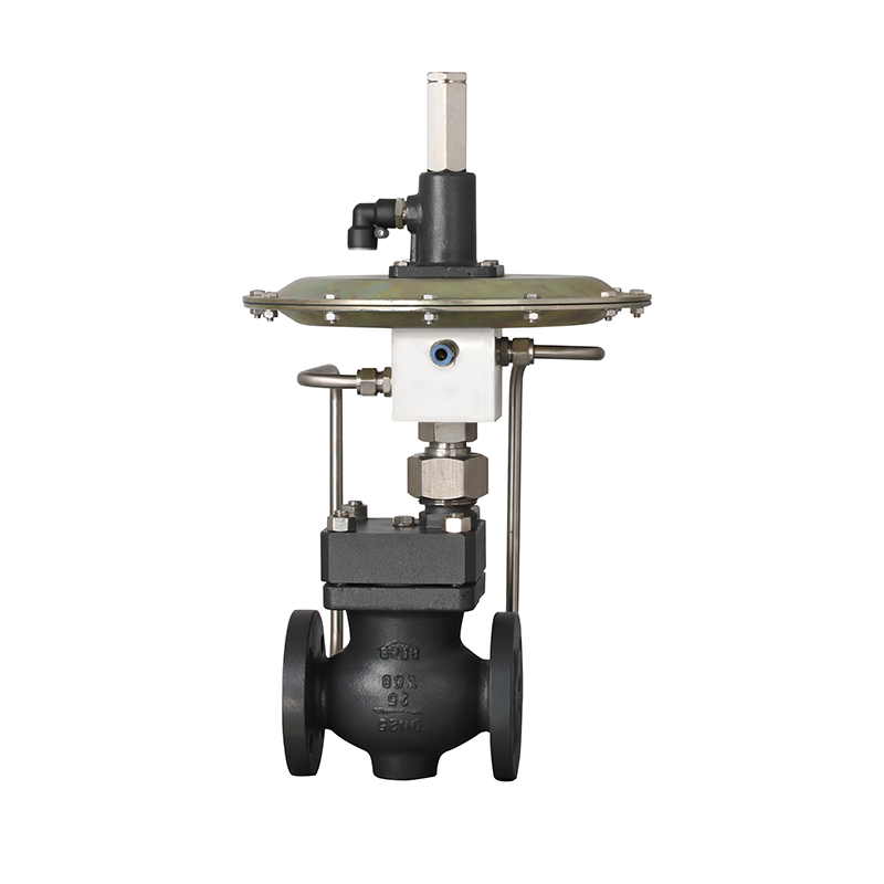
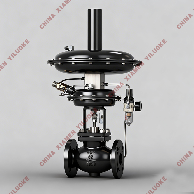
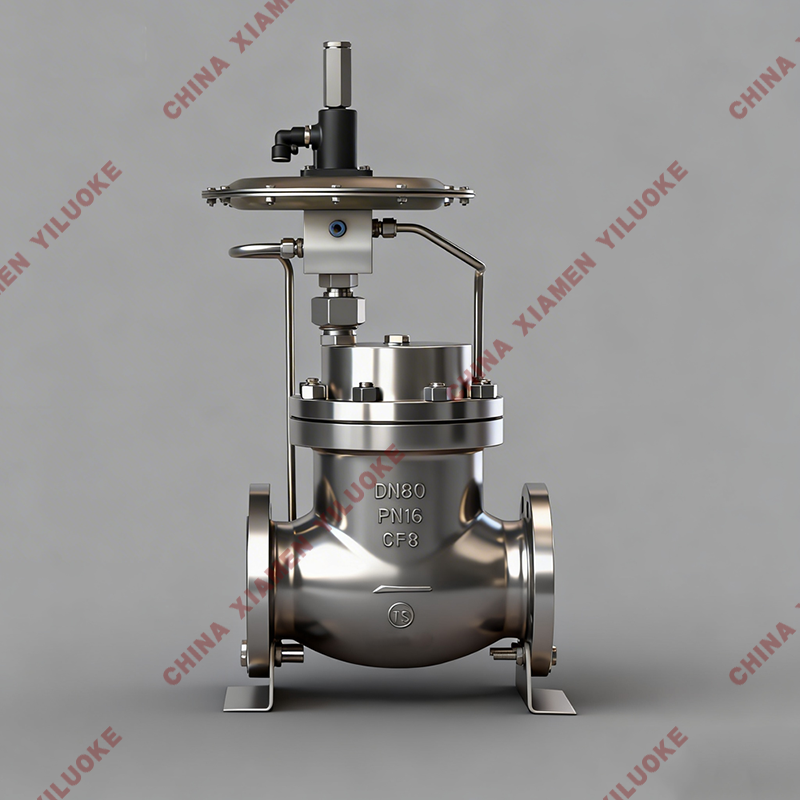
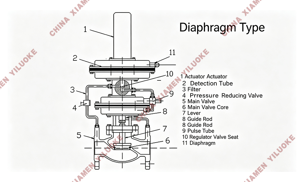
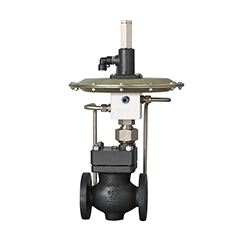
Self-operated micro pressure control valves and self-operated nitrogen blanketing valves require no external energy. They take the energy of the controlled medium as power source, introduce pressure into the diaphragm chamber of the actuator to generate thrust, and drive the movement of throttling elements to realize automatic regulation.
Self-operated micro pressure control valves and self-operated differential pressure control valves are mainly applied to gas combustion systems of various industrial furnaces to control the mixing flow ratio of two fuels for optimal combustion conditions. They are also used for pressure reduction, pressure stabilization and pressure relief regulation of various industrial media such as sealing oil and hydrogen in hydrogen-cooled generator sets, liquefied gas, oxygen and nitrogen, as well as gas blanketing for storage tanks of various oil products and chemical liquids.
Main Technical Parameters
Valve Body
Item | Specification |
Valve Body Type | Straight-through cast globe valve |
Nominal Diameter | DN20~200mm |
Nominal Pressure | PN1.0, 1.6MPa |
Flange Standard | ANSI, JIS, DIN, GB, JB; customized standards available upon request |
Connection Type | Flange (FF, RF, RTJ) |
Bonnet Type | Standard integrated type |
Gland Type | Bolt compression type |
Sealing Packing | V-type PTFE packing, PTFE-impregnated asbestos packing, asbestos textile packing, graphite packing |
Pressure Regulation Range (KPa) | 0.5~6, 5~10, 9~15, 12~19, 18~25, 22~30 28~35, 32~40, 38~50, 48~60, 58~72, 70~100 |
Minimum Differential Pressure for Normal Operation | ≥0.01MPa |
Operating Temperature | ≤80℃ |
Applicable Media | Gas, steam, low-viscosity liquid |
Internal Trim
Item | Specification |
Plug Type | Single-seat, sleeve plug |
Flow Characteristic | Linear |
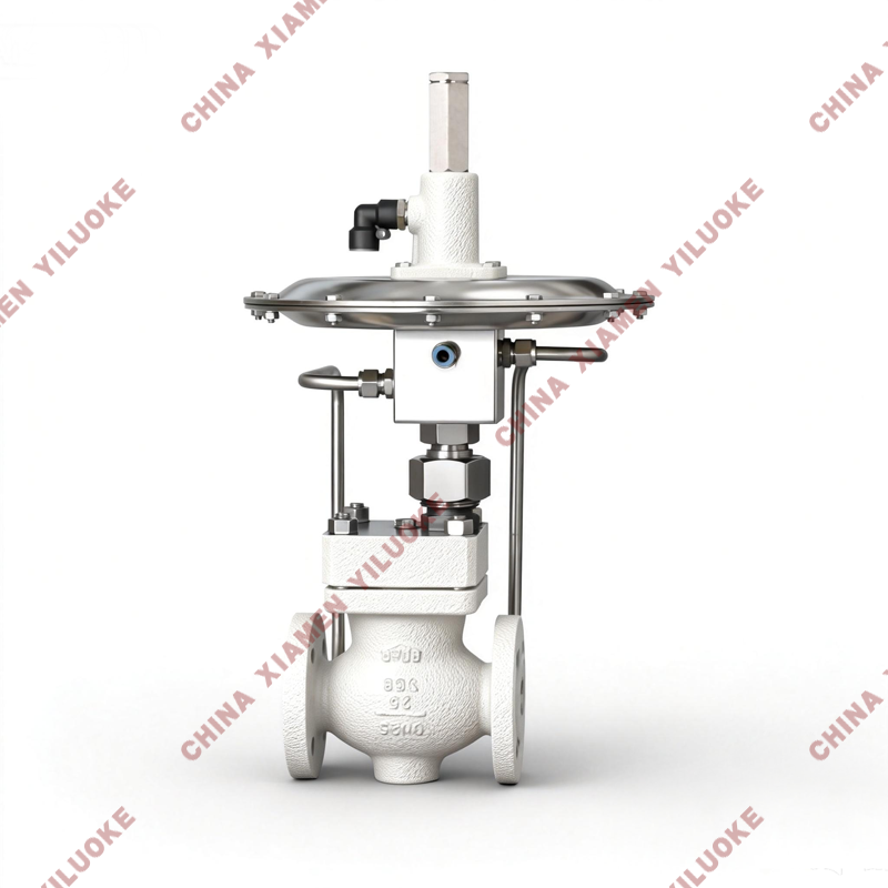
Main Component Materials & Structure Drawing
No. | Part Name | Material Option 1 | Material Option 2 | Material Option 3 | Material Option 4 |
1 | Valve Body | WCB | CF8 | CF8M | CF3M |
2 | Valve Seat | 304 | 304 | 316 | 316L |
3 | Gasket Core | 304 | 304 | 316 | 316L |
4 | Bonnet | Q235 | 304 | 316 | 316L |
5 | Valve Stem | 304 | 304 | 316 | 316L |
6 | Lower Diaphragm Cover | Q235 | — | — | — |
7 | Diaphragm | Fiber-reinforced EPDM or FKM | — | — | — |
8 | Upper Diaphragm Cover | Q235 | — | — | — |
9 | Gland | Q235 | — | — | — |
10 | Threaded Cover | Q235 | — | — | — |
Main Performance Indexes
Item | Parameter |
Regulation Accuracy | ≤10% |
Allowable Leakage (Under Specified Test Conditions) | Hard Seal: 4×0.01% of rated valve capacity Soft Seal leakage (L/h) by DN size: DN20:0.15, DN25:0.3, DN32:0.45, DN40:0.6, DN50:0.9, DN65:1.7, DN80:4.0, DN100:6.75 |
Rated Flow Coefficient & Allowable Differential Pressure
Nominal Diameter DN | 20 | 25 | 32 | 40 | 50 | 65 | 80 | 100 | 125 | 150 | 200 |
Rated Flow Coefficient Kv | 7 | 11 | 20 | 30 | 48 | 75 | 120 | 190 | 300 | 480 | 760 |
Allowable Differential Pressure (MPa, PN16) | 1.6 | 1.5 | 1.2 | — | — | — | — | — | — | — | — |
Format Note
All original text, parameter data and material information remain unchanged; unified table layout and hierarchical titles for foreign trade independent station display, diaphragm uniformly translated as diaphragm as required
Leave Your Message
Products categories
-
Pneumatic Micro‑Flow Control Valve
-
Electric Temperature Control Valve
-
Pneumatic High‑Pressure Control Valve
-
Electric High‑Pressure Control Valve
-
Self-Operated Micro Pressure Control Valve
-
Electric 3-Way Control Valve
-
Pneumatic Actuated 3-Way Control Valve
-
Electric Sleeve Control Valve
-
Intelligent Electric Control Valve