


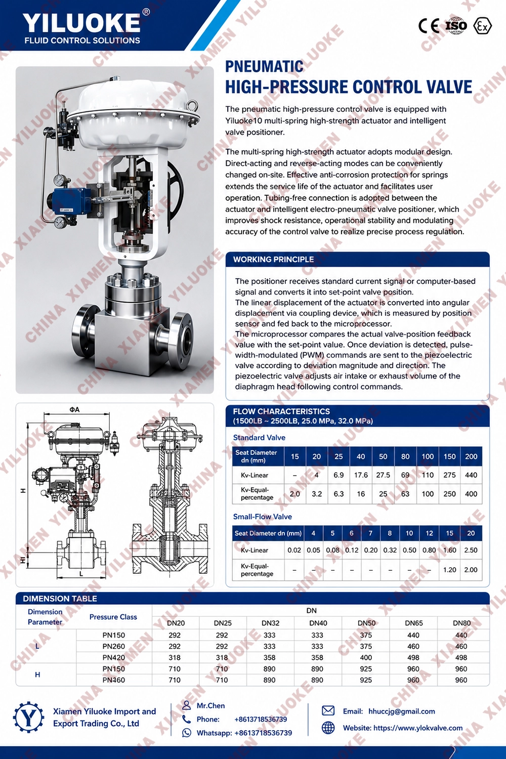
Pneumatic High‑Pressure Control Valve
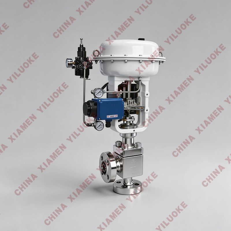
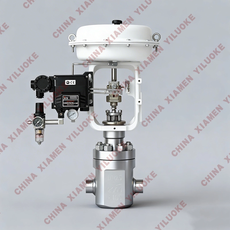
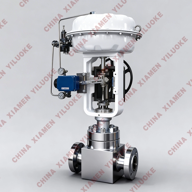
The pneumatic high‑pressure control valve consists of a straight‑stroke pneumatic diaphragm actuator and a low‑resistance straight‑through control valve body. It is a special valve designed for high‑pressure systems. Matched with pneumatic or electric regulating instruments (with electro‑pneumatic converter), it is applied for automatic regulation and remote control of process in chemical, petroleum, power and other industrial sectors. The pneumatic high‑pressure control valve is composed of pneumatic diaphragm actuator and high‑pressure control valve. Its action comes from the thrust generated by signal pressure acting on the diaphragm, pushing the stem and driving the valve core to move correspondingly to change valve travel. The variation of travel changes the flow area of the valve so as to regulate process parameters such as pressure, temperature, flow rate and liquid level.
Working Principle
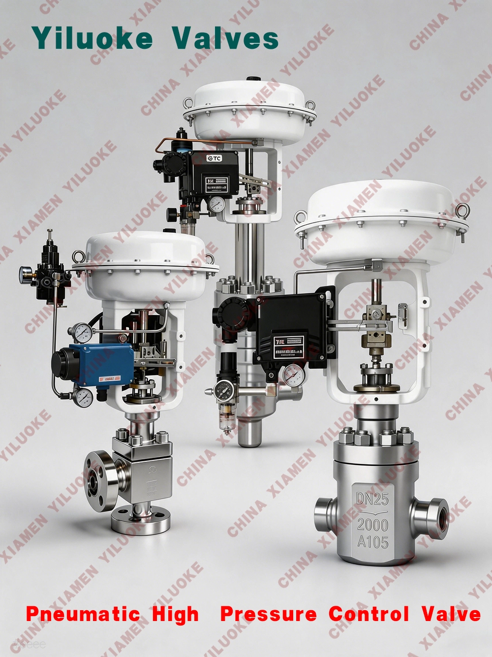
The pneumatic high‑pressure control valve adopts straight‑through single‑seat cage type structure with plunger‑shaped valve core. For high pressure difference service condition, hard alloy is infiltrated or embedded on the head of valve core to resist erosion and cavitation under high pressure difference and extend service life. Due to high pressure difference, medium creates large unbalanced force on valve core, so actuator with high rigidity is selected in design, and valve positioner is generally equipped.
Application Scenarios
The pneumatic high‑pressure control valve is especially suitable for regulating high‑viscosity fluid containing suspended solids and granular media, avoiding coking, adhesion and blockage.
Technical Parameters
| Nominal Diameter(DN) | 20 | 25 | 32 | 40 | 50 | 65 | 80 | 100 | 125 | 150 | 200 | 250 | 300 | |
| Seat Diameter(dn) | 20 | 25 | 32 | 40 | 50 | 65 | 80 | 100 | 125 | 150 | 200 | 250 | 300 | |
| Rated Flow Coefficient(KV) | Single Seat | 6.9 | 11 | 17.6 | 27.5 | 44 | 69 | 110 | 176 | 275 | 440 | 630 | 875 | 1250 |
| Cage Type | 6.3 | 10 | 16 | 25 | 40 | 63 | 100 | 155 | 250 | 370 | 580 | 900 | 1300 | |
| Allowable Pressure Difference(MPa) | ≤ Nominal Pressure | |||||||||||||
| Rated Stroke(mm) | 16, 25, 40, 60, 100 | |||||||||||||
| Matching Actuator Model | ZHA/B‑22 | ZHA/B‑23 | ZHA/B‑34 | ZHA/B‑45 | ZHA/B‑56 | |||||||||
| Valve Body Type | Straight‑through cast high‑pressure globe valve, angle‑type forged high‑pressure valve body | |||||||||||||
| Nominal Diameter | DN20~300mm | |||||||||||||
| Nominal Pressure | PN11.0, PN15.0, PN26.0, PN42.0MPa; ANSI 150, 300, 600, 900LB; JIS 10, 20, 30, 40K | |||||||||||||
| Flange Standard | GB/T9113, JB/T79, HG20594 and other standards | |||||||||||||
| Connection Type | Flange(FF RF RTJ), Welding(SW BW), Thread(for size within 1") | |||||||||||||
| Bonnet Type | Standard type(-17~+250℃), High temperature type(+250~+450℃), Low temperature type(-60~-196℃), Bellows seal type(-40~+350℃) | |||||||||||||
| Gland Type | Bolt compression type | |||||||||||||
| Sealing Packing | V‑type PTFE packing, PTFE‑impregnated asbestos packing, asbestos textile packing, graphite packing | |||||||||||||
| Valve Body Material | Forged steel(A105), stainless steel, chromium‑molybdenum steel | |||||||||||||
Pneumatic Diaphragm Actuator Parameters
| Matching Actuator Type | ZHA/B Multi‑spring Diaphragm Actuator | ||||
| Actuator Model | ZHA/B‑22 | ZHA/B‑23 | ZHA/B‑34 | ZHA/B‑45 | ZHA/B‑56 |
| Effective Area(cm²) | 350 | 350 | 560 | 900 | 1400 |
| Stroke(mm) | 10, 16 | 24 | 40 | 40, 60 | 100 |
| Spring Range(KPa) | 20~100(standard), 20‑60, 60‑100, 40‑200, 80‑240 | ||||
| Diaphragm Material | Nitrile rubber with nylon fabric, EPDM rubber with nylon fabric | ||||
| Air Supply Pressure | 140~400KPa | ||||
| Air Source Port | RC1/4" | ||||
| Ambient Temperature | -30~+70℃ | ||||
| Optional Accessories | Positioner, air filter regulator, lock‑up valve, limit switch, valve position transmitter, handwheel mechanism, etc. | ||||
| Action Type | Air‑to‑close(B) —‑ Valve opens on air loss(FO); Air‑to‑open(K) —‑ Valve closes on air loss(FC) | ||||
Performance Parameters
| Item | Without Positioner | With Positioner |
| Basic Error(%) | ±5.0 | ±1.0 |
| Hysteresis Error(%) | 3.0 | 1.0 |
| Dead Zone(%) | 3.0 | 0.4 |
| Start‑end Deviation(%) | Air‑to‑open: start point ±2.5, end point ±1.0; start point ±5.0, end point ±1.0 | |
| Air‑to‑close: start point ±5.0, end point ±2.5; start point ±1.0, end point ±1.0 | ||
| Rated Stroke Deviation(%) | ≤2.5 | |
| Leakage(L/h) | 0.01% × rated valve capacity | |
| Adjustable Range R | 30:1 | |
Structural Features
1. When high‑pressure medium enters the valve, pressure energy and noise are fully reduced inside the cage, so fluid will not erode sealing surfaces of valve core and seat, realizing anti‑erosion performance. The valve disc moves up and down to adjust flow rate arbitrarily with good adjustability.
2. Key components are made of high‑quality stainless steel for high temperature resistance, high pressure resistance and anti‑erosion performance. Hard Stellite alloy is overlaid on sealing parts of valve core and seat, and overlay thickness of sealing surface is no less than 2.5mm.
3. Contact between valve disc and cage generates no friction. Direct positioning of cage ensures tight valve closure without leakage and flexible opening without jamming.
4. Floating structure is adopted for valve stem and disc, which can solve scratching and leakage caused by stem misalignment during manufacturing.
5. Valve stem surface is treated by anti‑corrosion nitriding process with good rigidity, wear resistance and anti‑scratching performance.
6. Flexible graphite packing with nickel wire is adopted, soft and wear‑resistant, will not scratch valve stem.
7. Maximum flow capacity of this valve reaches 180T/H.
Maintenance & Operating Precautions
1. The valve shall be stored in dry and ventilated indoor space, and both ends of valve shall be blocked.
2. Valves for long‑term storage shall be inspected regularly to remove dirt. Special attention shall be paid to keep sealing surfaces clean and avoid damage.
3. Before installation, carefully check whether valve marks match application requirements.
4. Inspect valve cavity and sealing surfaces before installation. Wipe dirt with clean cloth if any.
5. Inspect main sealing surface and bypass sealing surface periodically after operation. Repair or replace timely once damaged or failed.
6. Bolts between valve body and bracket as well as bolts on packing gland may get loose due to long‑time pipeline vibration. Tighten bolts diagonally to prevent leakage.
Leave Your Message
Products categories
-
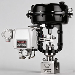
Pneumatic Micro‑Flow Control Valve
-
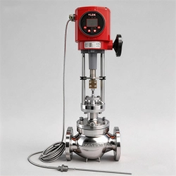
Electric Temperature Control Valve
-
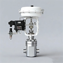
Pneumatic High‑Pressure Control Valve
-
Electric High‑Pressure Control Valve
-
Self-Operated Micro Pressure Control Valve
-
Electric 3-Way Control Valve
-
Pneumatic Actuated 3-Way Control Valve
-
Electric Sleeve Control Valve
-
Intelligent Electric Control Valve