


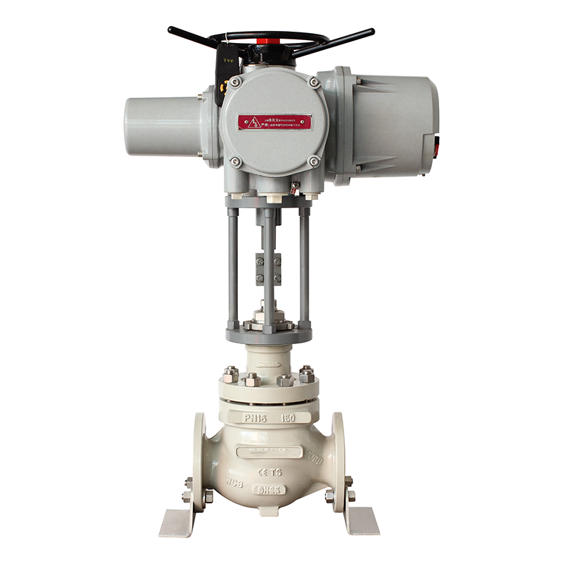
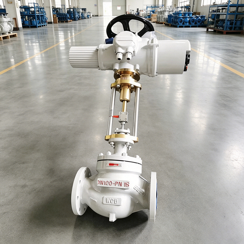
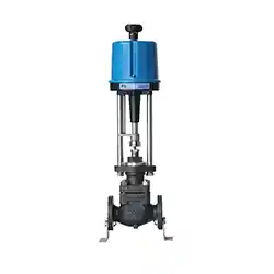
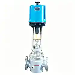
Intelligent Electric Control Valve
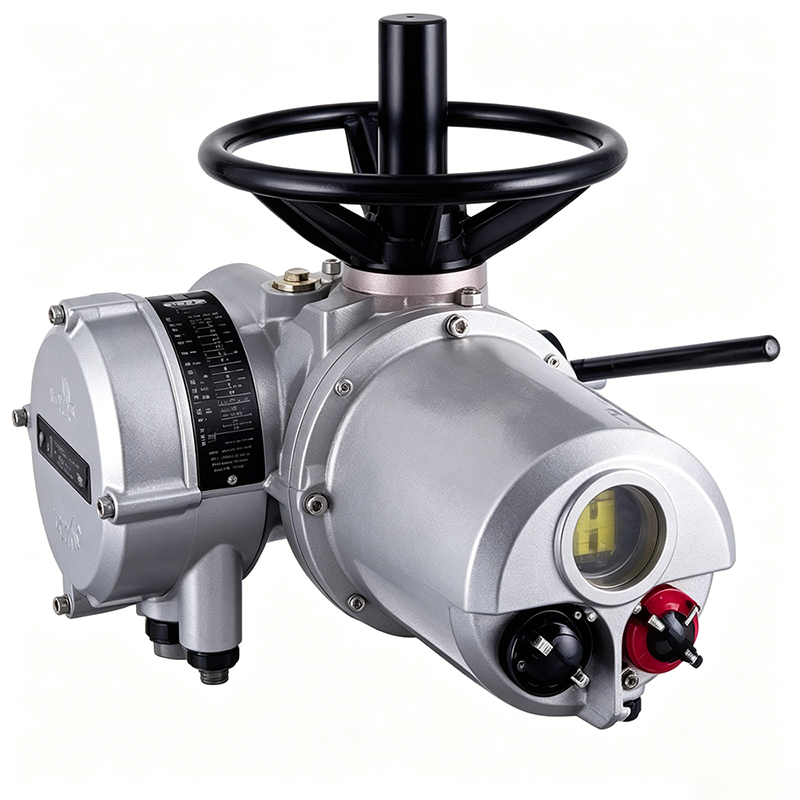
1. Electric Actuator Performance
1.1 Double Seal & Double Protection
The Electric Control Actuater housing features a protection rating of IP68 (3 meters underwater for 48 hours) and complies with NEMA4/4X/6 standards, achieving complete waterproof, dustproof and non-breathable performance. The Rotork dual-seal system provides comprehensive protection for internal components by isolating internal cables from the terminal box via waterproof terminal modules. Even when the terminal cover is removed during on-site wiring, continuous protection is maintained through the independent sealing structure of the terminal module, safeguarding internal components from external environmental interference at all times.
1.2 Non-intrusive Permanent Sealing
On-site commissioning of the IQ electric actuator requires no removal of the electrical box cover. All parameter setting and functional adjustment can be completed via the supporting infrared setter. The equipment is fully assembled in a factory controlled environment, eliminating internal gas exchange and realizing permanent sealing protection for all internal components. The non-intrusive control design removes all penetrating shafts through the control housing, fundamentally avoiding potential seal failure risks.
1.3 Simplified Structure & Upgraded Performance
The IQ actuator adopts an optimized and streamlined structural design. It simplifies redundant mechanical structures while fully expanding equipment specifications and operating performance, balancing structural simplicity, operational reliability and working condition adaptability.
1.4 High-precision Torque Measurement
The actuator can accurately and stably detect the operating force of the valve, serving as the core foundation for overload protection and stable operation of both valves and actuators. Equipped with Rotork patented output torque measurement system, the IQ actuator is developed based on mature industrial pressure sensor technology and fully verified in numerous industrial scenarios. Under loaded operating conditions, the piezoresistive sensor built in the torque sensor converts the reaction force of the motor worm thrust into an electrical signal proportional to the output torque. It delivers accurate and repeatable torque measurement results that are independent of power frequency, voltage and ambient temperature changes.
1.5 Precise Valve Position Measurement
Precise process control relies on accurate positioning at the end of the valve stroke, while hydraulic control depends on accurate positioning in the middle of the valve stroke. The patented non-contact valve position measurement system features an extremely simple and highly stable structure. A single-component resolver converts the rotational motion of the output center sleeve into an electrical signal, which is accurately compared with the limit parameters stored in a secure and permanent memory to achieve high-precision valve position control.
1.6 Reduced Components & Improved Operational Reliability
By optimizing the layout of mechanical and electrical systems and upgrading the handwheel structure and control chassis, the basic operational reliability of the equipment is significantly improved. The IQ control module adopts the latest system-on-chip technology, greatly reducing the number of electronic components and lowering the structural complexity of circuit interconnections, wiring and printed circuit boards. Integrated with enhanced functions including data display and multi-system protection, the overall operating performance and service reliability of the equipment are comprehensively improved.
1.7 High Safety Integrity
The IQ series actuators are specially developed to enhance the safety integrity of valve actuation systems. Through continuous structural optimization and technological innovation, it provides process engineers with customized solutions adaptable to different working conditions, supporting equipment selection based on specified safety integrity levels. The equipment complies with international process system safety assessment standards including IEC61508, ISA-S84.01 and DIN19250, and can provide matching solutions according to users’ actual working condition requirements.
2. Specifications & Technical Parameters of Intelligent Electric Control Valve
2.1 Nominal Diameter & Flow Coefficient (Kv)
Nominal Diameter DN(mm) | 20 | 25 | 32 | 40 | 50 | 65 | 80 | 100 | 125 | 150 | 200 | 250 | 300 | 350 | 400 |
Rated Flow Coefficient Kv | |||||||||||||||
Single-seat Valve (P) | 1.2~5.0 | 8 | 12 | 20 | 32 | 50 | 80 | 120 | 200 | 280 | 450 | - | - | - | - |
Double-seat Valve (N) | - | 10 | 16 | 25 | 40 | 63 | 100 | 160 | 250 | 400 | 630 | 1000 | 1600 | - | - |
Sleeve Valve (M) | - | 15 | - | 20 | 30 | - | 75 | 115 | - | 240 | 350 | - | - | - | - |
2.2 Basic Parameters
Nominal Pressure (MPa): 1.6, 4.0, 6.0
Stroke (mm): 10, 16, 25, 40, 60, 100
Control Signal: 0-10mA DC, 4-20mA DC
Medium Temperature (℃): Low temperature -250~-60; Normal temperature -40~+250; Medium temperature -40~+450; General -200~+200
Flow Characteristic: Linear, Equal Percentage
Adjustable Range: 30:1
2.3 Valve Body Material (Matched by Nominal Pressure & Working Temperature)
PN0.6MPa: Low temperature condition: ZG1Cr18Ni9Ti
PN1.6MPa: Normal temperature condition: ZG230-450; Low temperature condition: ZG1Cr18Ni9Ti
PN4.0MPa: Low temperature condition: ZG1Cr18Ni9Ti; Normal & medium temperature condition: ZG230-450, ZG1Cr18Ni9Ti
PN6.4MPa: Low temperature condition: ZG1Cr18Ni9Ti; Normal & medium temperature condition: ZG230-450, ZG1Cr18Ni9Ti
2.4 Structural & Material Supporting Parameters
Flange Standard: Standard: JB78-59, JB79-59; Customizable: JB/79.1-94, ANSI, JIS, DIN and other domestic & international standards
Plug Material: 1Cr18Ni9, SS304, 0Cr18Ni12Mo2Ti, SS316, ZG1Cr18Ni9Ti
Bonnet Type: Ordinary type (normal temperature), Fin type (medium temperature), Extended neck type (low temperature)
3. Main Technical Performance Indicators
Test Item | Technical Index |
Basic Error | ±5.0% |
Hysteresis | ≤3.0% |
Dead Zone | ≤3.0% |
Leakage (Single-seat Valve) | Grade IV per JB/T7387-94, less than 10 of rated valve capacity |
Leakage (Double-seat Valve) | Grade III per JB/T7387-94, less than 10 of rated valve capacity |
Leakage (Sleeve Valve) | Grade III per JB/T7387-94, less than 10 of rated valve capacity |
4. Allowable Pressure Difference Parameters
Working Condition: Valve plug flow-open state, valve back pressure P2=0 when fully closed; Note: The allowable pressure difference of double-seat valves and sleeve valves is ≤ nominal pressure; the allowable pressure difference of single-seat valves refers to the table below.
Nominal Diameter DN(mm) | Seat Diameter (mm) | Actuator Effective Thrust (N) | Allowable Pressure Difference @PN1.6 (MPa) | Allowable Pressure Difference @PN6.4 (MPa) |
3/4 | 3/4/5/6/7/8/10/12/15/20 | 400, 1000, 2500 | 3.8, 2.7, 1.7, 1.0 | 4.3, 4.3, 2.5 |
25 | 26 | 400, 1000, 2500 | 0.5 | 0.6, 3.6 |
32 | 32 | - | 0.4 | 0.4, 2.3 |
40 | 40 | 400, 1000, 2500, 6400 | 0.7, 1.0 | 0.7, 1.5 |
50 | 50 | - | 0.5, 1.0 | 0.5, 1.0 |
65 | 66 | 6400, 16000 | 1.4 | 1.4 |
80 | 80 | - | 1.0 | 1.0 |
100 | 100 | - | 0.6 | 0.6 |
125 | 125 | 6400, 16000 | 0.5, 1.0 | 0.5, 1.0 |
150 | 150 | - | 0.3, 0.7 | 0.3, 0.7 |
200 | 200 | - | 0.2, 0.4 | 0.2, 0.4 |
250 | - | 16000 | 0.3 | 0.3 |
300 | - | - | 0.2 | 0.2 |
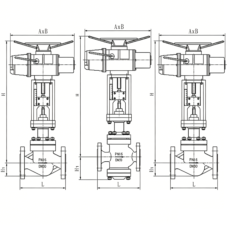
5. Overall Dimension Parameters (Unit: mm)
5.1 Electric Single-seat & Double-seat Control Valve (ZRZP/ZRZN)
DN | Actuator Width A | B | L(PN1.6) | L(PN4.0) | L(PN6.4) | H (Standard) | H (Fin Type) | H1 (ZRZP Single-seat) | H1 (ZRZN Double-seat) |
20 | 230 | 460 | 180 | 185 | 190 | 653 | 804 | / | / |
25 | - | - | 185 | 190 | 205 | 665 | 816 | 99 | 104 |
32 | - | - | 200 | 210 | 220 | 671 | 822 | 105 | 107 |
40 | - | - | 220 | 230 | 240 | 683 | 834 | 116 | 126 |
50 | 230 | 530 | 250 | 255 | 265 | 698 | 849 | 131 | 131 |
65 | - | - | 275 | 285 | 295 | 789 | 949 | 165 | 175 |
80 | - | - | 305 | 310 | 325 | 792 | 952 | 173 | 190 |
Leave Your Message
Products categories
-

Intelligent Electric Control Valve
-
Electric Single-Seat Control Valve
-
Electric Insulation Jacket Control Valve
-
Pilot Operated Self-operated Control Valve
-
Pneumatic Bellows Sealed Control Valve
-

Pneumatic Cryogenic Control Valve
-
Pneumatic Diaphragm Control Valve
-
Self-Operated Flow Control Valve
-
Self-Operated Temperature Control Valve