


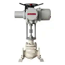
Electric Temperature Control Valve
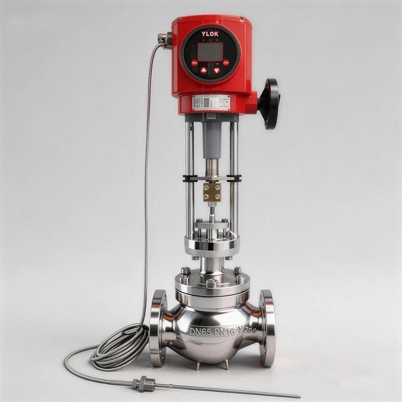
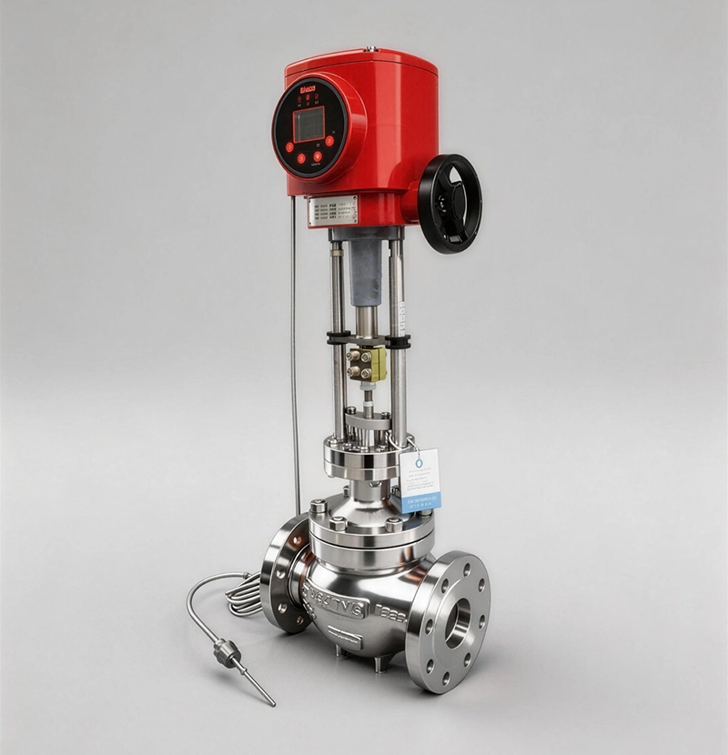
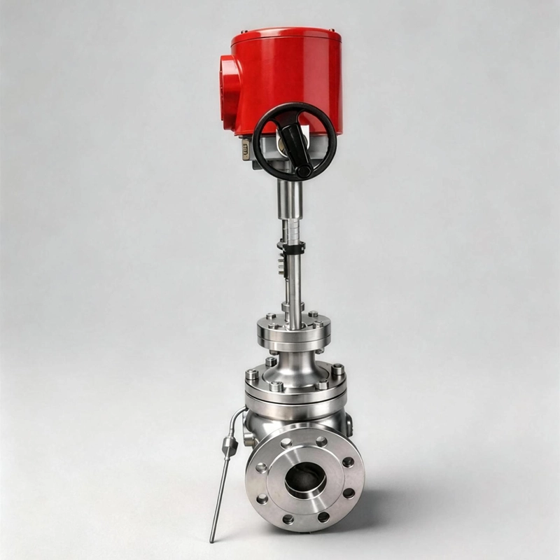
Electric Temperature Control Valves are divided into heating type and cooling type according to application purposes. The Electric Temperature Control Valve is suitable for large‑diameter pipelines and thermal oil control. Its biggest feature is that it only requires ordinary 220V power supply. It utilizes the self‑energy of the controlled medium to automatically adjust and control the temperature of steam, hot water, hot oil, gas and other media. It can also be applied for overheating prevention and heat exchange occasions. Featuring simple structure and convenient operation, it offers wide temperature adjustment range, fast response and reliable sealing performance, and supports random adjustment during operation. It is widely used for hot‑water supply in chemical, petroleum, food, textile, hotel and restaurant industries.
Electric Temperature Control Valves are mainly applied for temperature control of liquid, gas and steam in various cooling systems. For heating type, the valve closes when the controlled medium temperature rises. For cooling type, the valve opens when the controlled medium temperature rises.
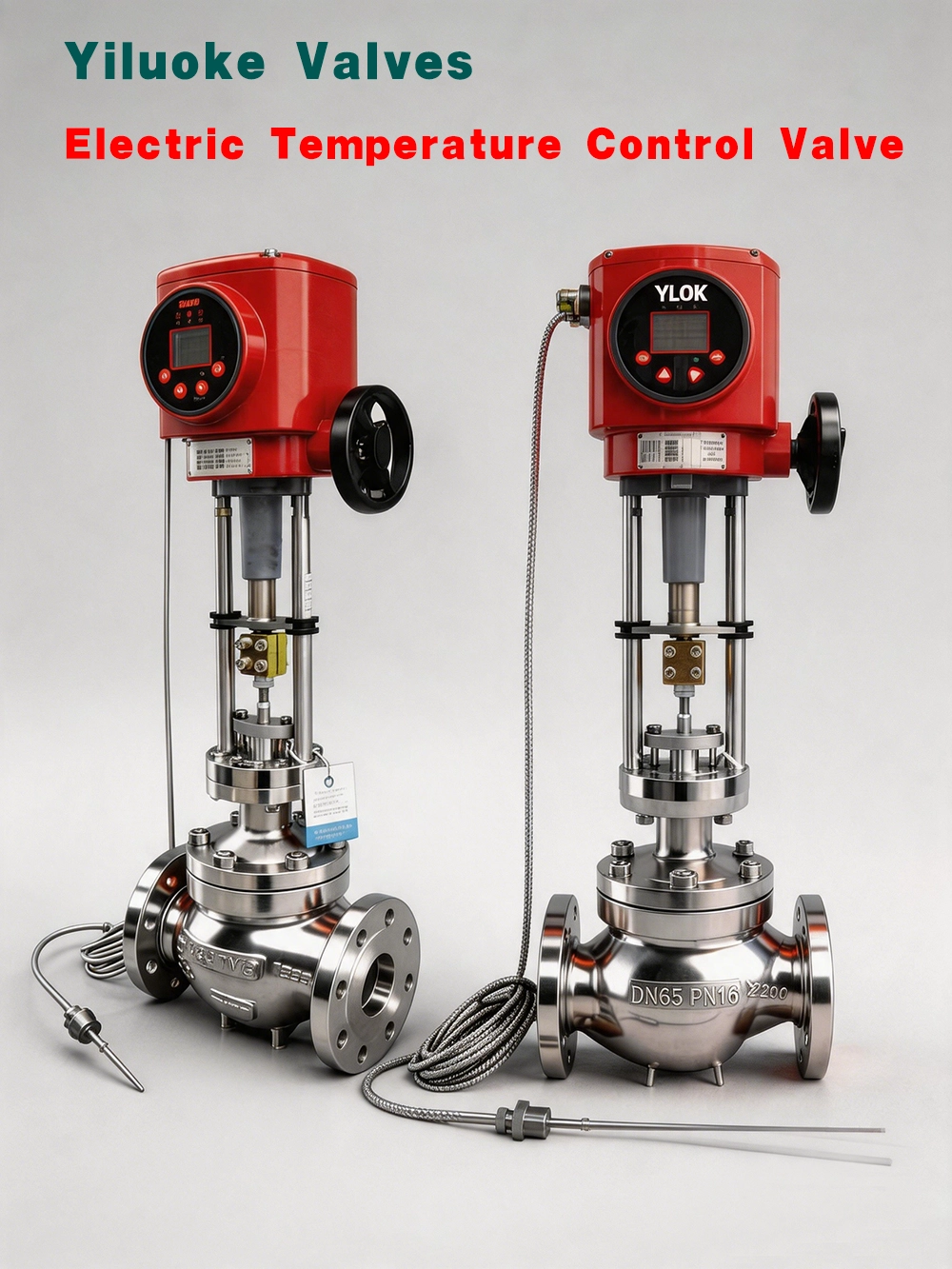
Working Principle
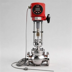
The Electric Temperature Control Valve consists of control valve body, electric actuator, temperature sensor and temperature regulator. It is available in heating type and cooling type for different requirements. Before operation, the main valve core stays at half‑open position and the sensor remains in natural state. After power‑on, the main valve core opens fully. Medium flows into the main valve body in arrow direction and heats the heat storage tank through valve core. When temperature reaches the set value, the sensor outputs linear signal to the integrated actuator, which drives stem and valve core to move and close the main valve core to stop heating. When temperature drops below set value, the sensor sends linear signal to the integrated actuator to gradually open the valve core. Medium flows into the heat storage tank in parabolic characteristic for reheating until target temperature is reached. In this way, the controlled medium is kept within preset temperature range to realize temperature regulation.
Main Parts Material
| Component Name | Material |
| Valve Body & Valve Cover | HT200, ZG230‑450, ZG1Cr18Ni9Ti |
| Valve Core | ZG1Cr18Ni9Ti, Stellite alloy overlay reinforced PTFE |
| Packing | PTFE, Flexible Graphite |
| Push Rod & Bushing | 2Cr13 |
| Gasket | Rubber asbestos sheet, 10#, 1Cr18Ni9Ti asbestos wound gasket |
| Bellows | 1Cr18Ni9Ti |
Structural Characteristics
1. Digital display for measured temperature, concise and intuitive.
2. Temperature setting is finished outside the actuator for easy parameter configuration.
3. Reasonable upper and lower electrical limit function, weak‑current control, safe and durable.
4. Robust and compact mechanical structure, simple wiring, installation, adjustment and maintenance.
5. Zero‑point and full‑stroke sensitivity can be adjusted easily via potentiometer.
6. V‑ring high‑temperature sealing assembly is adopted for valve body sealing to avoid stem jamming or gas leakage.
7. The actuator is equipped with three protection functions: overload protection, temperature protection and compression spring for tight valve closing.
8. The controller, key component of modulating actuator, adopts advanced hybrid integrated circuit with aging treatment. It is resin‑sealed in box shape, moisture‑proof, shock‑proof, compact and highly reliable.
Main Technical Parameters of Electric Temperature Control Valve
1. Valve Body
| Item | Specification |
| Valve Body Type | Regulating valve body |
| Nominal Diameter | DN20~200mm |
| Nominal Pressure | PN1.6, 2.5, 4.0, 6.4 |
| Flange Standard | GB/T9113, JB/T79, HG20594 and other standards |
| Connection Type | Flange(FF RF RTJ), Welding(SW BW), Thread(for size within 1 inch) |
| Bonnet Type | Standard:‑17~+250℃, High‑temp:+250~+450℃, Low‑temp:‑60~‑196℃, Bellows seal:‑40~+350℃ |
| Gland Type | Bolt‑tightened type |
| Sealing Packing | V‑shape PTFE packing, PTFE‑impregnated asbestos packing, asbestos textile packing, graphite packing |
| Valve Body Material | Cast steel(WCB), Stainless steel(CF8, CF8M, CF3, CF3M), Cr‑Mo steel, WCB lined with F46 |
2. Internal Trim Parts
| Item | Specification |
| Valve Core Type | Single‑seat plunger type |
| Flow Characteristic | Linear, Equal percentage |
| Valve Core Material | PTFE, Stainless steel(304, 304L, 316, 316L) |
3. Actuator, Sensor and Capillary Tube
| Item | Specification |
| Actuator Model | 3810 series, PSL series |
| Power Supply | 220V/50Hz |
| Input Signal | 4‑20mA or 1‑5V DC |
| Output Signal | 4‑20mA DC |
| Protection Class | IP55 |
| Explosion‑proof Mark | ExdⅡBT4 |
| Manual Operation | Handwheel |
| Ambient Temperature | -25~+70℃ |
| Ambient Humidity | ≤95% |
| Thermal Bulb & Capillary Material | H62, 1Cr18Ni9Ti |
| Capillary Length | 3m, 5m, 10m |
| Temperature Control Range | 0~250℃ |
| Set‑point Deviation | ±2℃ |
Rated Stroke, Flow Capacity and Leakage Standard
| Nominal Diameter | 20 | 25 | 32 | 40 | 50 | 65 | 80 | 100 | 125 | 150 | 200 |
| Flow Capacity(m³/h) | 7 | 10 | 16 | 25 | 40 | 63 | 100 | 160 | 250 | 400 | 630 |
| Rated Stroke(mm) | 6 | 8 | 10 | 14 | 20 | 30 | 30 | 40 | |||
| Regulation Accuracy(℃) | ±1 ~ ±5 | ||||||||||
| Applicable Medium | Steam, Water, Oil, Gas | ||||||||||
| Hard‑seal Allowable Leakage | 10‑4 × rated valve capacity | ||||||||||
| Soft‑seal Allowable Leakage | Zero leakage | ||||||||||
Maintenance Methods for Electric Temperature Control Valve
1. Regularly inspect pipelines for rust, welding slag, dirt and dust.
2. Frequently check supports and support brackets for heavy‑weight or vibration‑prone installation positions.
3. Ensure stable power supply without faults.
4. Replace the sealing gasket between valve body and upper bonnet in time after long‑time service. New gasket can be installed after removing upper bonnet only.
5. Replace packing immediately if leakage occurs at stuffing box. Disconnect valve stem, take out pressure plate and gland, then install new packing.
6. Carry out periodic inspection and maintenance.
7. When stored for long‑term, install protective cover for connecting flanges and block all ports with plastic plugs. Keep the valve in vertical or horizontal position.
8. Do not support the valve on sensitive components such as valve positioner, joints and connecting cables.
Leave Your Message
Products categories
-
Pneumatic Micro‑Flow Control Valve
-
Electric Temperature Control Valve
-
Pneumatic High‑Pressure Control Valve
-
Electric High‑Pressure Control Valve
-
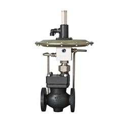
Self-Operated Micro Pressure Control Valve
-
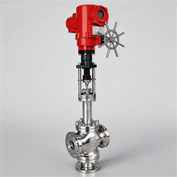
Electric 3-Way Control Valve
-
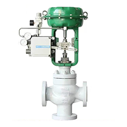
Pneumatic Actuated 3-Way Control Valve
-
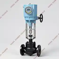
Electric Sleeve Control Valve
-
Intelligent Electric Control Valve