


PTFE Lined Diaphragm Valve
1. Product Overview
PTFE lined diaphragm valve is a special type of shut-off valve developed in the 1920s. Its closing member is a soft diaphragm that separates the inner cavity of valve body from bonnet cavity and driving components, hence named diaphragm valve.
Its core feature: the diaphragm isolates the lower valve body cavity from upper bonnet cavity. Components like stem and disc above the diaphragm are free from medium corrosion. It removes packing sealing structure and eliminates medium external leakage.
Diaphragm made of rubber, plastic and other soft sealing materials provides excellent tightness. Diaphragm is a vulnerable part and shall be replaced regularly according to medium properties.
Restricted by diaphragm material, this valve is only suitable for low pressure and relatively low temperature working conditions.
Classified by structure: weir type, straight flow type, globe type, straight through type, gate plate type and angle type. Flanged connection is standard. Drive modes include manual, electric and pneumatic. Pneumatic type is further divided into normally open, normally closed and reciprocating.
Not applicable for pipelines with temperature above 60℃, organic solvent, strong oxidizing medium or high pressure service.
Diaphragm valves are applied to open or block air flow in fluid systems with pressure ranging from 1.3×10⁻⁵ Pa to 2.5×10⁶ Pa.
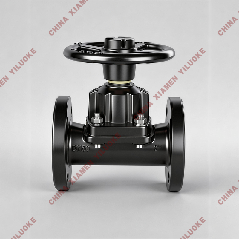
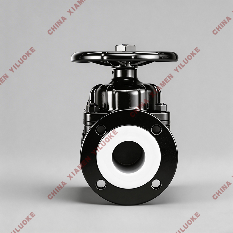
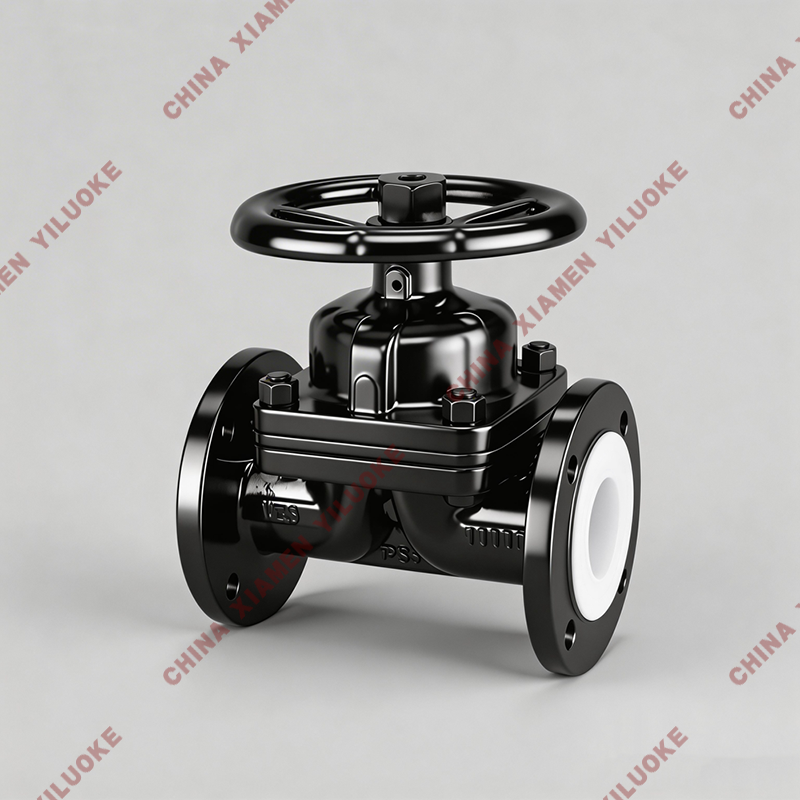
2. Product Image
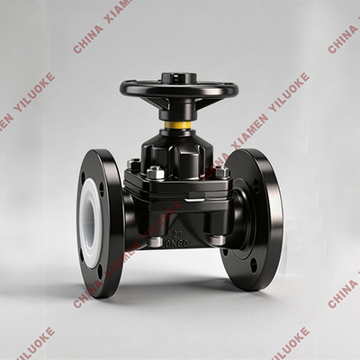
PTFE Lined Diaphragm Valve
3. Parts & Materials
Part Name | Gray Cast Iron (Z) | Cast Steel (C) | Stainless Steel (P/R) | Ultra-Low Carbon Stainless Steel (PL/RL) |
Body & Bonnet | HT250 | WCB | CF8 / CF8M | CF3 / CF3M |
Ball | WCB | WCB | CF8 / CF8M | CF3 / CF3M |
Lining / Seat | FEP(F46), PCTFE(F3), PFA | FEP(F46), PCTFE(F3), PFA | FEP(F46), PCTFE(F3), PFA | FEP(F46), PCTFE(F3), PFA |
Gland Flange | HT250 | WCB | CF8 / CF8M | CF3 / CF3M |
Packing | PTFE (Teflon) | PTFE (Teflon) | PTFE (Teflon) | PTFE (Teflon) |
Stud Bolt | 35 | 35 | 1Cr17Ni2 | 1Cr18Ni9 |
Nut | 45 | 45 | 0Cr18Ni9 | 0Cr18Ni9 |
Handwheel | WCC | WCC | WCC | WCC |
4. Execution Standards
Item | Standard |
Design Standard | GB12239 |
Face-to-Face Dimension | JB1688, GB12221 |
Flange Standard | JB/T79-94, GB9113.1~26 |
Inspection & Test Standard | GB/T13927 |
Drive Mode | Manual, Electric, Pneumatic, Normally Closed, Normally Open |
5. Structure Drawing
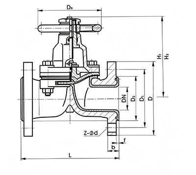
PTFE Lined Diaphragm Valve Structure Diagram
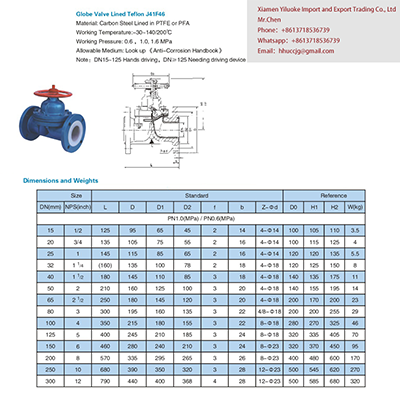
6. Connection Dimension Table
Unit: mm
PN0.6MPa / PN1.0MPa
DN | NPS | L | D | D1 | D2 | f | b | Z-φd | d0 | H | H1 | WT(kg) |
15 | 1/2 | 125 | 95 | 65 | 45 | 2 | 14 | 4-φ14 | 100 | 105 | 110 | 3.5 |
20 | 3/4 | 135 | 105 | 75 | 55 | 2 | 16 | 4-φ14 | 100 | 115 | 125 | 4 |
25 | 1 | 145 | 115 | 85 | 65 | 2 | 16 | 4-φ14 | 120 | 120 | 135 | 5.5 |
32 | 1 1/4 | 160 | 135 | 100 | 78 | 2 | 18 | 4-φ18 | 120 | 125 | 150 | 8 |
40 | 1 1/2 | 180 | 145 | 110 | 85 | 3 | 18 | 4-φ18 | 140 | 135 | 175 | 11 |
50 | 2 | 210 | 160 | 125 | 100 | 3 | 20 | 4-φ18 | 140 | 155 | 195 | 14 |
65 | 2 1/2 | 250 | 180 | 145 | 120 | 3 | 20 | 4-φ18 | 200 | 170 | 200 | 23 |
80 | 3 | 300 | 195 | 160 | 135 | 3 | 22 | 4-φ18 | 200 | 200 | 255 | 29 |
100 | 4 | 350 | 215 | 180 | 155 | 3 | 22 | 8-φ18 | 280 | 270 | 325 | 46 |
125 | 5 | 400 | 245 | 210 | 185 | 3 | 24 | 8-φ18 | 320 | 335 | 405 | 70 |
150 | 6 | 460 | 280 | 240 | 210 | 3 | 24 | 8-φ23 | 320 | 370 | 450 | 95 |
200 | 8 | 570 | 335 | 295 | 265 | 3 | 26 | 8-φ23 | 400 | 480 | 600 | 170 |
250 | 10 | 680 | 390 | 350 | 320 | 3 | 28 | 12-φ23 | 500 | 545 | 620 | 270 |
300 | 12 | 790 | 435 | 395 | 362 | 4 | 24 | 12-φ23 | 500 | 585 | 680 | 320 |
PN1.6MPa
DN | NPS | L | D | D1 | D2 | f | b | Z-φd | d0 | H | H1 | WT(kg) |
15 | 1/2 | 130 | 95 | 65 | 45 | 2 | 14 | 4-φ14 | 120 | 110 | 115 | 4 |
20 | 3/4 | 150 | 105 | 75 | 55 | 2 | 16 | 4-φ14 | 120 | 120 | 130 | 5 |
25 | 1 | 160 | 115 | 85 | 65 | 2 | 16 | 4-φ14 | 140 | 125 | 140 | 6 |
32 | 1 1/4 | 180 | 135 | 100 | 78 | 2 | 18 | 4-φ18 | 140 | 130 | 155 | 9 |
40 | 1 1/2 | 200 | 145 | 110 | 85 | 3 | 18 | 4-φ18 | 160 | 140 | 180 | 12 |
50 | 2 | 230 | 160 | 125 | 100 | 3 | 20 | 4-φ18 | 160 | 160 | 200 | 15 |
65 | 2 1/2 | 290 | 180 | 145 | 120 | 3 | 20 | 4-φ18 | 200 | 175 | 205 | 24 |
80 | 3 | 310 | 195 | 160 | 135 | 3 | 22 | 8-φ18 | 200 | 205 | 260 | 30 |
100 | 4 | 350 | 215 | 180 | 155 | 3 | 24 | 8-φ18 | 280 | 275 | 330 | 48 |
125 | 5 | 400 | 245 | 210 | 185 | 3 | 26 | 8-φ18 | 320 | 340 | 410 | 75 |
150 | 6 | 480 | 280 | 240 | 210 | 3 | 28 | 8-φ23 | 320 | 375 | 460 | 105 |
200 | 8 | 600 | 335 | 295 | 265 | 3 | 30 | 12-φ23 | 400 | 485 | 605 | 182 |
250 | 10 | 730 | 405 | 355 | 320 | 3 | 32 | 12-φ25 | 500 | 550 | 625 | 295 |
300 | 12 | 850 | 460 | 410 | 375 | 4 | 34 | 12-φ25 | 500 | 590 | 685 | 345 |
Format Instruction
All chapter headers adopt uniform H2 format consistent with previous valve documents
Full content retained without deletion; all tables standardized
Professional unified term: PTFE Lined Diaphragm Valve
Dimensions, material grades, national standards fully reserved original data