


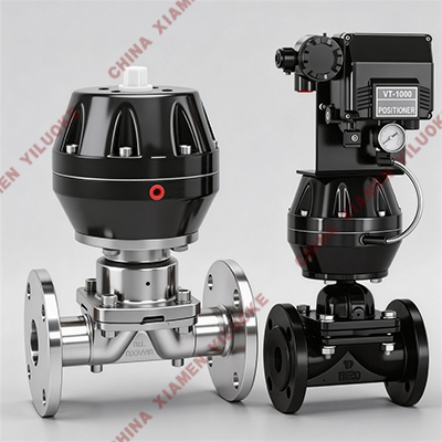
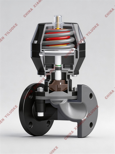
Pneumatic Actuated Diaphragm Valve
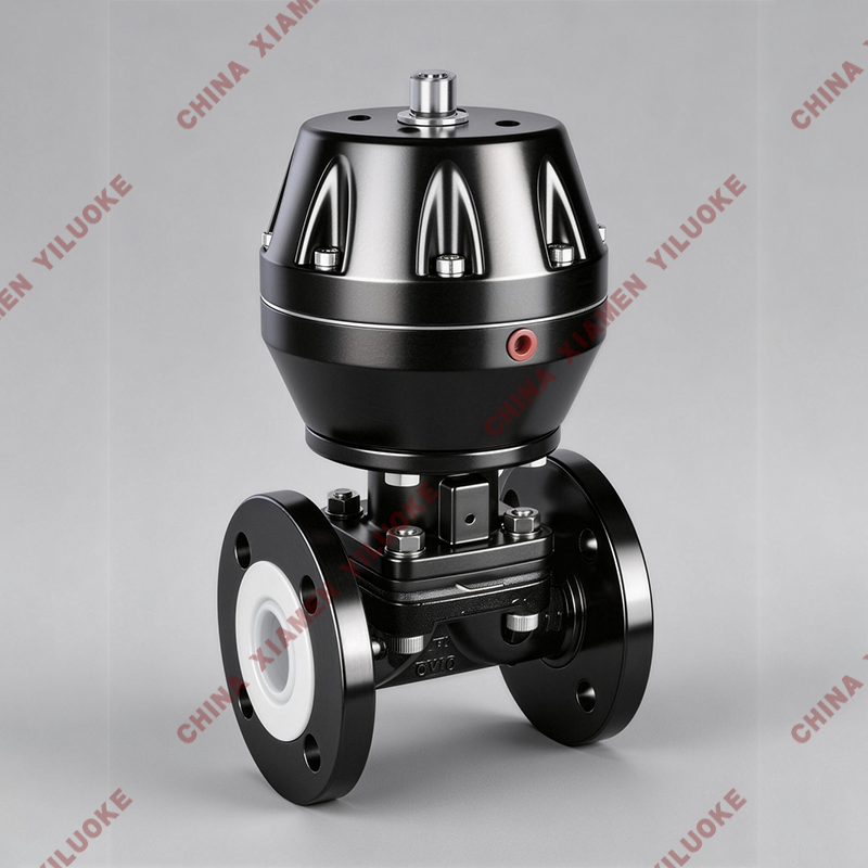
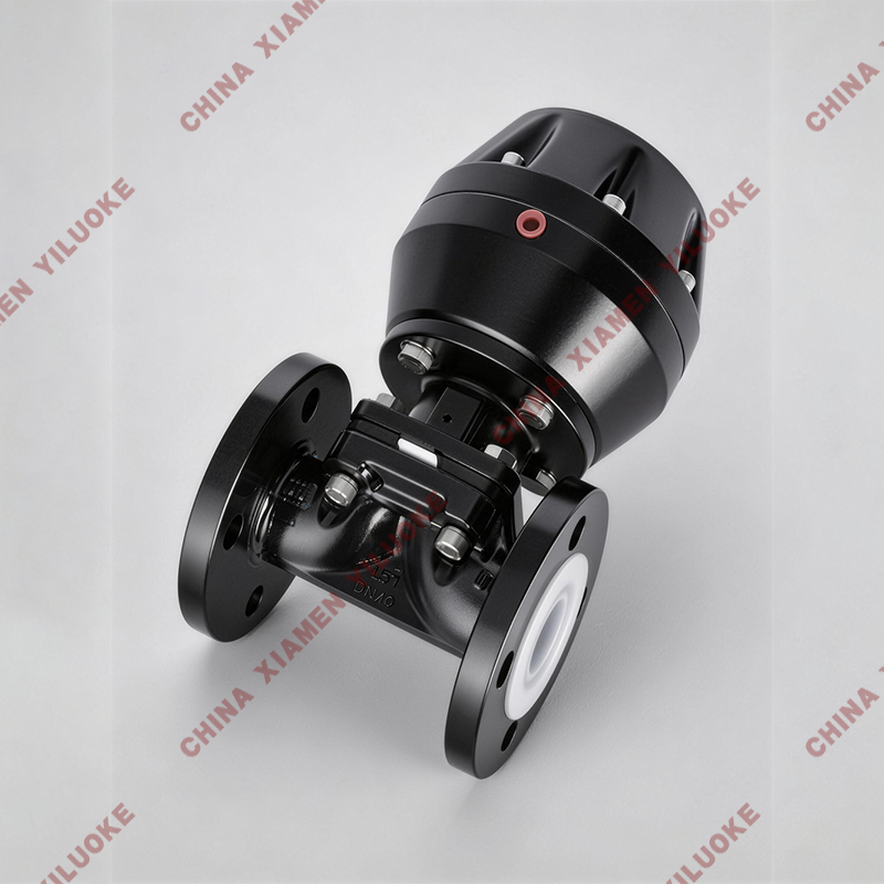
Pneumatic Actuated diaphragm valve is a special type of shut-off valve. Its opening and closing component is a diaphragm made of soft material, which separates the inner cavity of the valve body from the inner cavity of the bonnet and driving parts, hence the name Pneumatic Actuated diaphragm valve. Its most prominent feature is that the diaphragm isolates the lower valve body cavity from the upper bonnet cavity. Parts such as stem and disc above the diaphragm will not be corroded by medium. It eliminates the packing sealing structure and avoids medium leakage. Application: This valve is used to control non-corrosive or general corrosive media. The inner surface of valve body can be unlined or lined with various optional rubbers to match different operating temperatures and fluid pipelines.
Working Principle of Pneumatic Actuated Diaphragm Valve
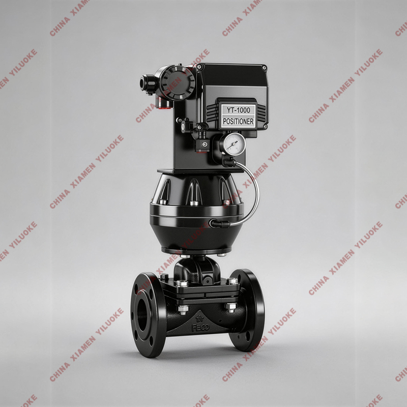
The opening and closing of diaphragm valve is realized by pipeline pressure acting on reinforced rubber diaphragm. When pressure medium enters the control chamber of the valve, the diaphragm is pressed down to close the flow passage. When the pressure inside control chamber is exhausted to atmosphere or downstream pipeline, the diaphragm rises to open the passage. The valve has no stem, sealing gasket or guide seat. The only moving part inside flow channel is diaphragm, so rusting and jamming are avoided for higher stability. Multiple structural and control types are available to meet various fluid control requirements.
Basic Technical Parameters
Item | Specification |
Driving Medium | Compressed air, 4–6 bar |
Nominal Diameter | DN15–DN200 mm |
Nominal Pressure | 1.0 MPa |
Operating Temperature | -10℃ ~ 60℃ |
Connection Type | Flanged |
Valve Body Material | Cast iron, cast steel |
Diaphragm Material | PTFE, EPDM |
Applicable Medium | All kinds of water treatment media |
Actuator Material | Aluminum alloy |
Installation Direction | Any angle |
Optional Accessories | Limit switch, positioner, solenoid valve, pressure reducing valve |
Overall & Flange Dimension Table
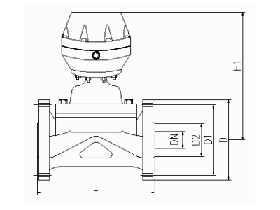
Nominal Diameter DN | Height H1 | Flange Outer Diameter D1 | Flange Bolt Circle Diameter D | Body Length L | Number of Flange Bolts n | Bolt Size C | Flange Thickness B |
15 | 125 | 65 | 95 | 125 | 4 | 14 | 14 |
20 | 130 | 75 | 105 | 135 | 4 | 14 | 16 |
25 | 145 | 85 | 115 | 145 | 4 | 14 | 16 |
32 | 180 | 100 | 135 | 160 | 4 | 18 | 16 |
40 | 220 | 110 | 145 | 180 | 4 | 18 | 16 |
50 | 250 | 125 | 160 | 210 | 4 | 18 | 18 |
65 | 280 | 145 | 180 | 250 | 4 | 18 | 22 |
80 | 340 | 160 | 195 | 300 | 4 | 18 | 25 |
100 | 370 | 180 | 215 | 350 | 8 | 18 | 25 |
125 | 420 | 210 | 245 | 400 | 8 | 18 | 30 |
150 | 480 | 240 | 280 | 460 | 8 | 23 | 30 |
200 | 625 | 295 | 335 | 570 | 8 | 23 | 35 |