


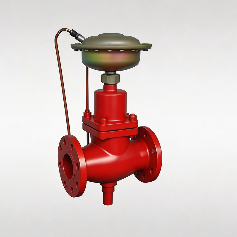
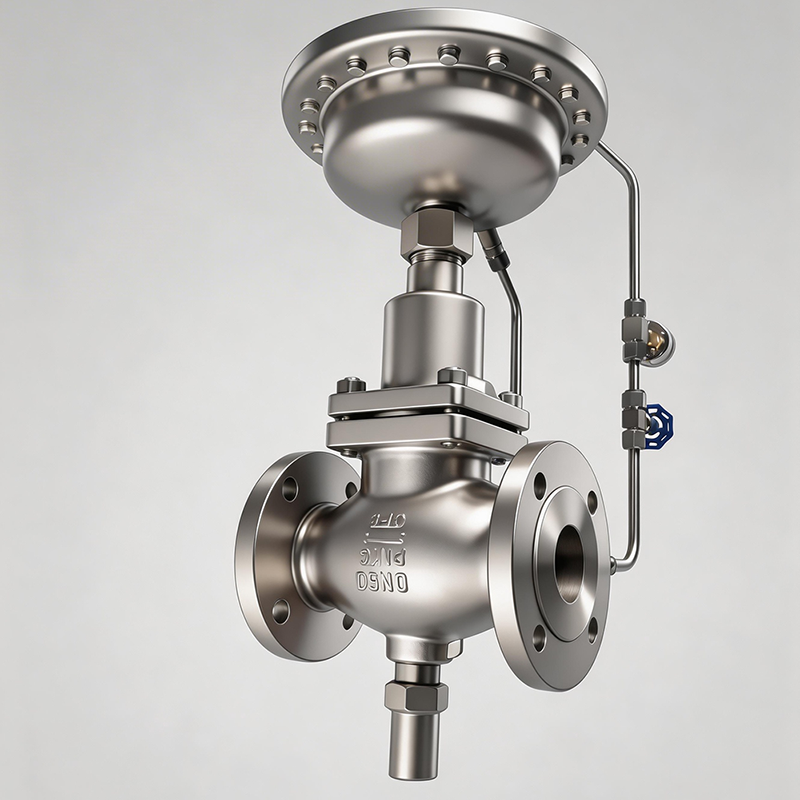
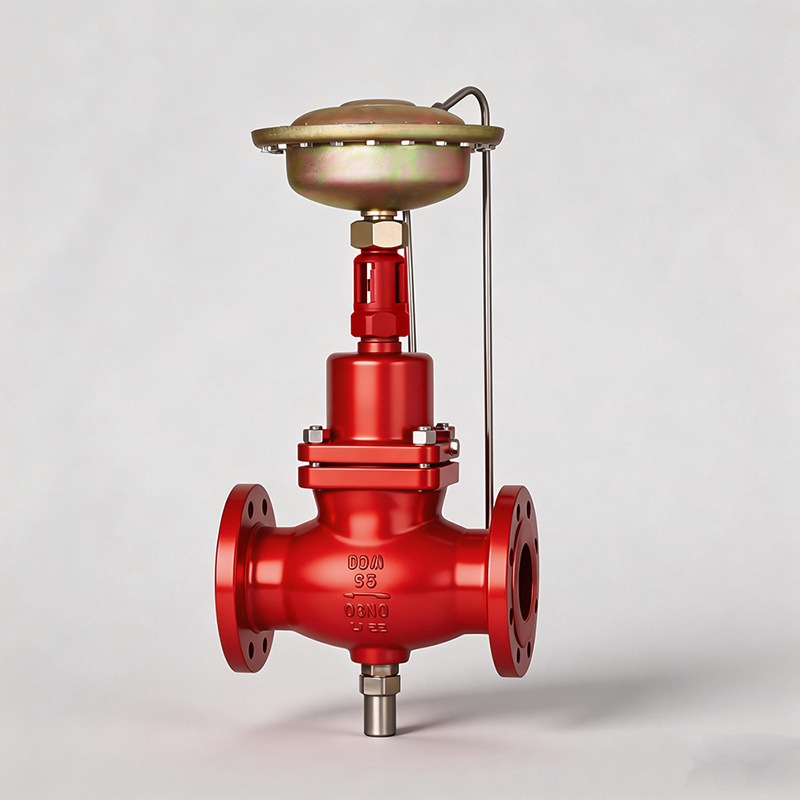
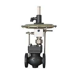
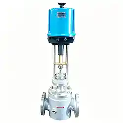
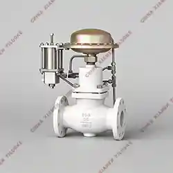
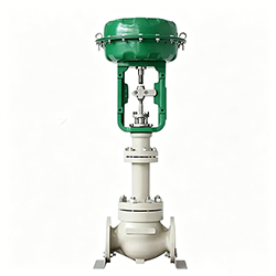
Self-Operated Flow Control Valve
1. Product Overview
The self-operated flow control valve is an energy-saving control valve that requires no external energy source. It is designed for flow control of non-corrosive liquid, gas, steam and other media in industrial process equipment. It is widely applicable to automatic control systems without available external driving energy in various industrial production processes.
2. Technical Features
No external driving energy required: Operates purely by medium self-energy, energy-saving and environmentally friendly.
Built-in pressure balance structure: Ensures high sensitivity and stable regulation performance.
Maintenance-free & reliable performance: Simple structure, stable operation and long service life.
Low noise & smooth operation: Optimized flow channel design reduces fluid noise and vibration.
Modular design: High level of standardization, serialization and generalization for flexible assembly and convenient replacement.
3. Main Technical Parameters
Parameter Item | Specification |
Main Material | WCB, CF8, CF8M |
Nominal Diameter | DN15~DN250 |
Nominal Pressure | PN1.6~PN4.0MPa |
Pressure Regulation Range | 0.02MPa, 0.05MPa |
Max Working Temperature | ≤200℃ |
Driving Mode | Self-pressure sampling type |
Bonnet Type | Standard type: -17℃ ~ +450℃ |
Gland Style | Bolt compression type |
Packing | V-type PTFE packing, PTFE-impregnated asbestos packing, woven asbestos packing, graphite packing |
Plug Type | Single-seat plug, cage plug |
Flow Characteristic | Linear |
3.1 Allowable Differential Pressure
PN16: 1.6MPa, 1.5MPa, 1.2MPa, 1.0MPa
PN40: 2.0MPa
4. Flow Performance Parameters
DN(mm) | 15 | 20 | 25 | 32 | 40 | 50 | 65 | 80 | 100 | 125 | 150 | 200 | 250 |
Rated Flow Coefficient Kvs | 4 | 6.3 | 8 | 16 | 20 | 32 | 50 | 80 | 125 | 160 | 280 | 320 | 400 |
Max Flow @0.02MPa (m³/h) | 1.5 | 2.5 | 3.5 | 5.5 | 9.0 | 14 | 22 | 36 | 55 | 70 | 125 | 180 | 250 |
Max Flow @0.05MPa (m³/h) | 2.5 | 3.5 | 5.5 | 9.0 | 12 | 22 | 36 | 55 | 85 | 110 | 180 | — | — |
Noise Coefficient Z | 0.6 | 0.6 | 0.6 | 0.55 | 0.55 | 0.5 | 0.5 | 0.45 | 0.4 | 0.35 | 0.3 | 0.2 | 0.2 |
5. Actuator Technical Parameters
Parameter Item | Specification 1 | Specification 2 |
Effective Diaphragm Area (cm²) | 250 | 630 |
Throttle Pressure Difference (MPa) | 0.02 | 0.05 |
Max Differential Pressure Between Upper & Lower Diaphragm Chambers (MPa) | 0.4 | 0.15 |
Actuator Material
Diaphragm Cover: Galvanized steel plate; Diaphragm: EPDM / FKM with fiber reinforcement
Control Tubing & Fittings
Tubing: Copper pipe / Steel pipe, 10×1mm; Compression Fitting: R1/4"
6. Main Performance Index
Control Accuracy: ±5%
Allowable Leakage Rate (Under specified test conditions)
Hard Seal: 4 × 0.01% of valve rated capacity
Soft Seal:
DN15~DN50: 10 bubbles/min
DN65~DN125: 20 bubbles/min
DN150~DN250: 40 bubbles/min
7. Application Scope
This valve is suitable for automatic control systems without external driving energy in water supply, petrochemical, heating, energy, papermaking, food processing, steel and other industrial fields. It is especially applicable to automatic control devices for natural gas production & transmission and coal gas conveying systems.
Leave Your Message
Products categories
-
Self-Operated Micro Pressure Control Valve
-
Electric 3-Way Control Valve
-
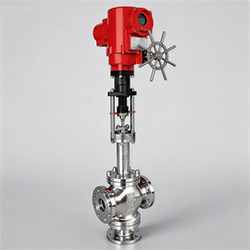
Pneumatic Actuated 3-Way Control Valve
-

Electric Sleeve Control Valve
-
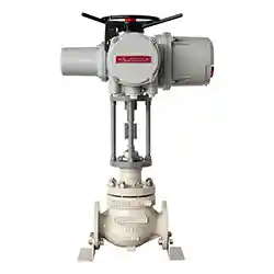
Intelligent Electric Control Valve
-
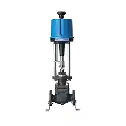
Electric Single-Seat Control Valve
-
Electric Insulation Jacket Control Valve
-
Pilot Operated Self-operated Control Valve
-
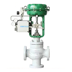
Pneumatic Bellows Sealed Control Valve