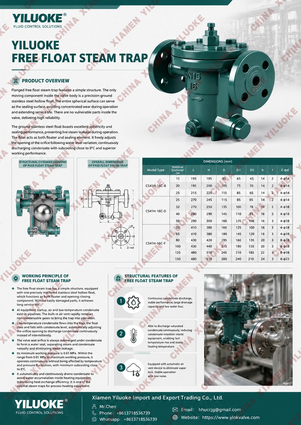


Free Float Steam Trap


The free float steam trap is a mechanical type steam trap with a hollow spherical float as the core sensing component. When condensate enters the valve body, the float rises with the liquid level to open the discharge orifice and drain condensate automatically. When steam flows in, the float sinks to seal the orifice, preventing steam leakage. This trap features simple structure, stable operation, strong resistance to water hammer, and high steam tightness. It is widely used in heating equipment, heat exchangers, steam pipelines and other industrial steam systems for continuous condensate removal. It is applicable to working conditions with fluctuating pressure and variable condensate flow, effectively improving thermal efficiency and saving steam consumption.
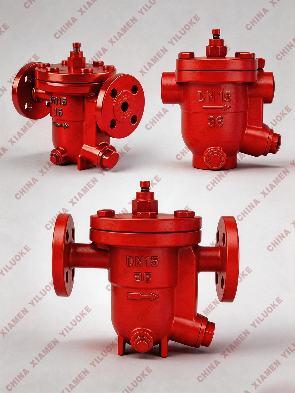
Core Advantages of Free Float Steam Trap
It is not affected by fluctuations in pressure, temperature, or condensate flow, enabling continuous drainage (draining immediately when there is water). With a minimum subcooling degree of 0℃, it can make heating equipment achieve optimal working efficiency. Its minimum working pressure is 0.01MPa, and the maximum backpressure rate is ≤85%.
This product is the most ideal steam trap for industrial heating equipment in petroleum, chemical, printing and dyeing, pharmaceutical, papermaking, food, and other industries.
Specifications and Technical Parameters
| Nominal Pressure (PN) | 1.6-4.0MPa |
| Maximum Operating Temperature (TMO) | 350℃ |
| No-load Air Leakage Rate | Less than 3% |
| Subcooling Degree | 0.5℃ |
| Maximum Operating Pressure | To be supplemented |
Working Principle of Free Float Steam Trap
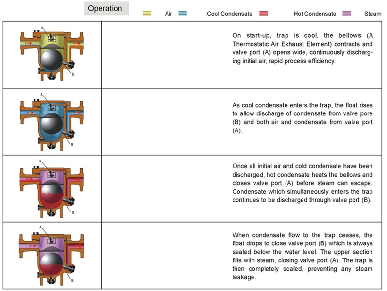
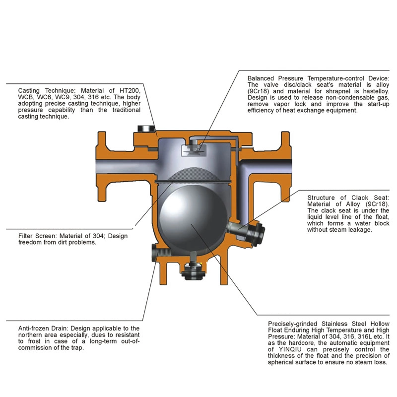
The free float steam trap has a simple structure, with only one precision-ground stainless steel hollow float inside. The float serves both as a floater and an opening/closing component, with no wearing parts, ensuring a long service life.
When the device is just started, air and low-temperature condensate appear in the pipeline. The manual air vent valve can quickly discharge non-condensable gases, and the steam trap starts to work. Low-temperature condensate flows into the trap, the liquid level of the condensate rises, the float rises, and the valve opens.
The device quickly increases the temperature. Before the temperature in the pipeline rises to the saturation temperature, the automatic air vent valve has been closed.
The device enters normal operation: the amount of condensate decreases, the liquid level drops, and the float adjusts the orifice flow according to the liquid level rise and fall.
When the condensate stops entering, the float approaches the valve seat along the medium flow direction, and the valve closes.
The valve seat of the free float steam trap is always below the liquid level, forming a water seal and preventing steam leakage.
Parts Drawing
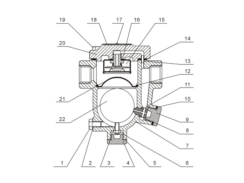
Working Parts Drawing of Free Float Steam Trap
| No. | Name | Material | No. | Name | Material |
|---|---|---|---|---|---|
| 1 | Blowdown Plug | Carbon Steel | 2 | Blowdown Plug Gasket | Copper |
| 3 | Adjusting Screw | Carbon Steel | 4 | Plug | Carbon Steel |
| 5 | Plug Gasket | Stainless Steel | 6 | Adjusting Screw Gasket | Stainless Steel |
| 7 | Valve Body | Cast Steel | 8 | Valve Seat Gasket | Copper |
| 9 | Valve Seat Plug | Cast Steel | 10 | Valve Seat Plug Gasket | Stainless Steel |
| 11 | Valve Seat | Stainless Steel | 12 | Retaining Ring | Carbon Steel |
| 13 | Connecting Pipe | Stainless Steel | 14 | Bonnet Gasket | Stainless Steel |
| 15 | Air Vent Assembly | Stainless Steel | 16 | Air Vent Assembly Gasket | Copper |
| 17 | Rivet | Stainless Steel | 18 | Nameplate | Stainless Steel |
| 19 | Bonnet Bolt | Carbon Steel | 20 | Bonnet | Cast Steel |
| 21 | Strainer | Stainless Steel |
Fault Diagnosis & Solutions
| Symptom | Cause Description | Valve Disassembly Required | Diagnosis | Solution |
|---|---|---|---|---|
| No condensate drainage | Float cannot rise | No | Working pressure difference exceeds designed pressure of valve seat | Check nameplate parameters |
| Yes | Water enters inside the float | Replace the float | ||
| Yes | Air blockage caused by faulty air vent assembly | Replace air vent assembly | ||
| Small discharge capacity | Float rises but flow rate is insufficient | No | Working pressure difference is too low | Check flow chart according to valve seat size |
| Yes | Strainer blocked by impurities | Clean the strainer | ||
| Yes | Inlet & outlet pipeline blocked | Remove blockages | ||
| Continuous steam discharge | Float cannot fit closely against valve seat orifice | No | Incorrect installation orientation | Refer to installation drawing |
| Yes | Valve seat orifice deformed or blocked | Clean or replace valve seat | ||
| Yes | Deformed float or surface covered with dirt film | Replace the float | ||
| Yes | Impurities accumulated at valve chamber bottom | Clean impurities | ||
| Steam leakage | Leakage at positions other than main valve disc | No | Incorrect installation direction | Install horizontally |
| Yes | Impurities inside air vent assembly | Clean impurities | ||
| Yes | Sand holes on valve body | Replace valve body | ||
| Yes | Gasket leakage | Replace gasket or fasten bolts | ||
| Damaged float | Caused by water hammer | Yes | Unstable working pressure fluctuation or improper pipeline layout | Check operating conditions and piping layout |