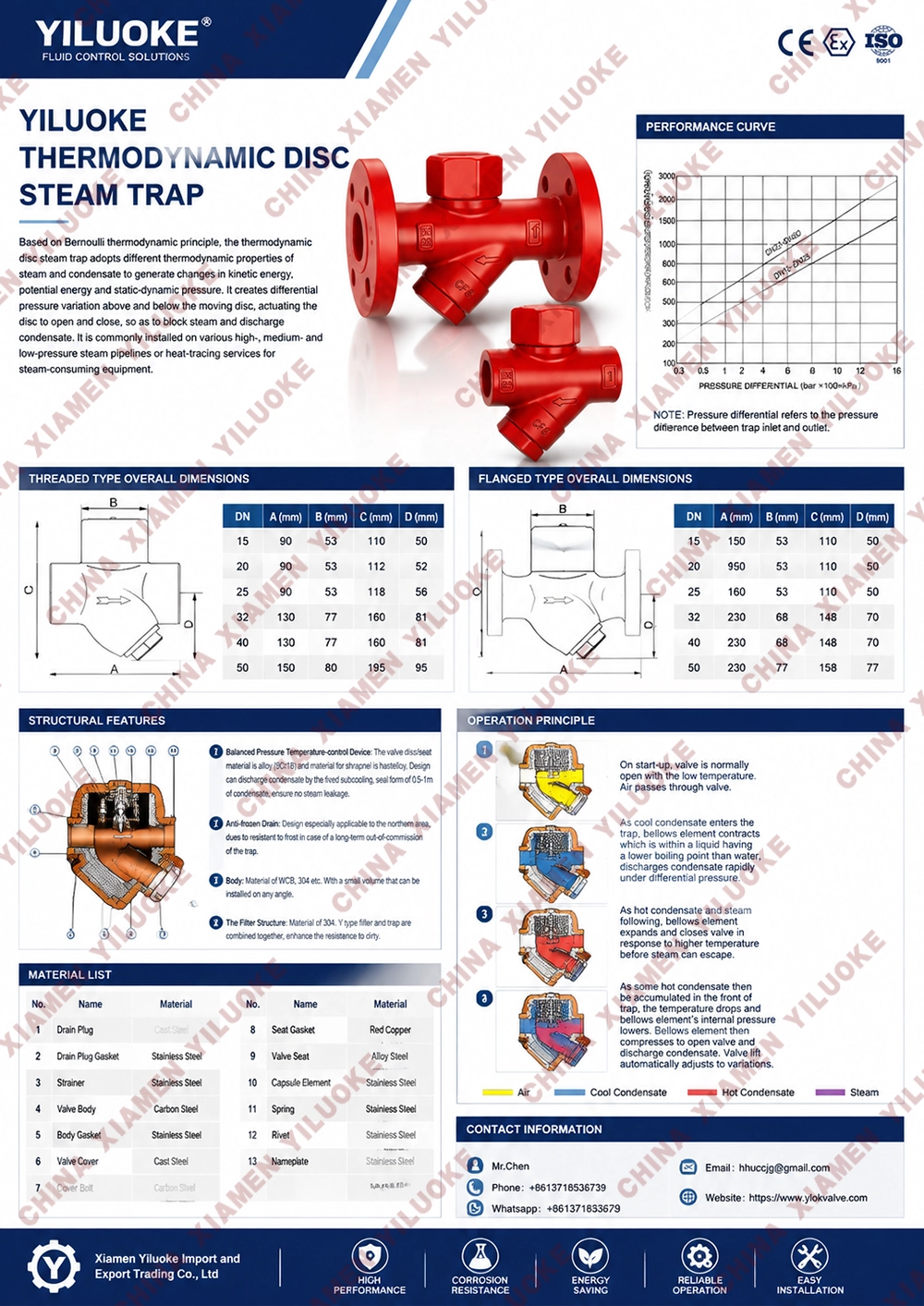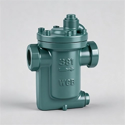


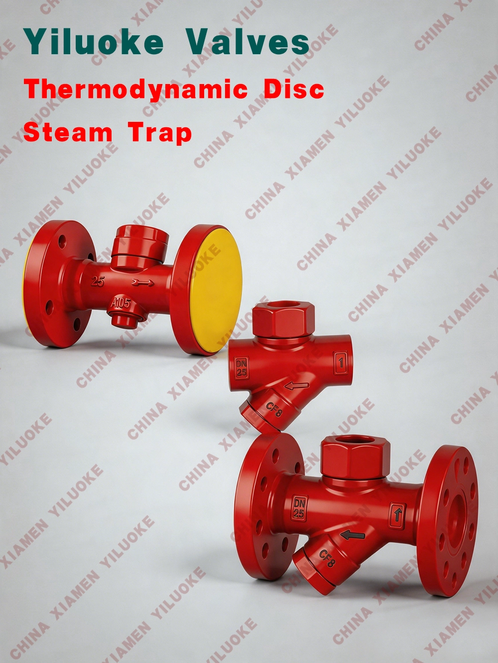
Thermodynamic Disc Steam Trap


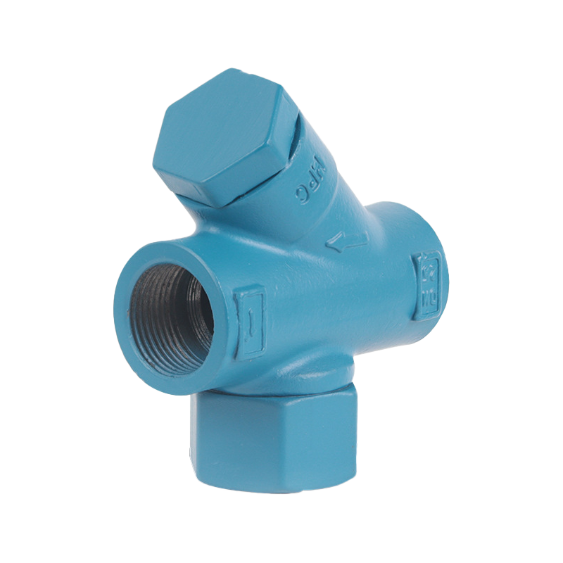
The thermodynamic disc steam trap utilizes different thermodynamic properties caused by changes in flow velocity and volume when steam and condensate pass through the valve orifice to drive the disc to open and close the seat orifice, so as to block steam and discharge condensate. The thermodynamic disc steam trap features intermittent and cyclic operation. The trap mechanism composed of disc and seat ring opens for several seconds to discharge condensate, then keeps closed for a long period until a new discharge cycle starts. All thermodynamic steam traps are disc‑type, which can reduce steam leakage and minimize problems caused by adhesion of internal dirt and impurities. The disc steam trap has a wide range of applications, suitable for various occasions such as steam main lines, tracing pipelines and steam heating equipment.
Working Principle
There is a disc inside the thermodynamic disc steam trap, which acts as both temperature‑sensitive component and actuator. When the equipment starts up, cooling condensate appears in the pipeline. The condensate pushes open the disc under working pressure and is discharged rapidly. After condensate is completely drained, steam flows into the trap. The volume of steam expands rapidly and steam flows faster than condensate, creating pressure difference above and below the disc. The disc closes quickly under the suction force of steam flow. When closed, the disc bears pressure on both sides. The force‑bearing area under the disc is smaller than that on the upper side. Since the pressure inside the trap chamber comes from steam pressure, the upward force on the disc is greater, and the disc is tightly closed. When steam inside the trap chamber cools down into condensate, the chamber pressure disappears. Condensate pushes the disc open under working pressure and drainage resumes. The valve works in cycles for intermittent drainage.
Technical Parameters
| Nominal Pressure | PN16 | PN25 | PN40 |
| Air‑lock Prevention Function | Self‑control | Self‑control | Self‑control |
| PMA Max Allowable Pressure | 1.6Mpa(38℃) | 2.5Mpa(38℃) | 4.1Mpa(38℃) |
| PMO Operating Pressure | 1.3Mpa(315℃) | 2.0Mpa(200℃) | 2.5Mpa(200℃) |
| TMA Max Allowable Temperature | 300℃(1.1Mpa) | 300℃(1.1Mpa) | 300℃(2.6Mpa) |
| TMO Operating Temperature | 250℃(1.1Mpa) | 250℃(1.1Mpa) | 250℃(2.6Mpa) |
| Product Model | CS49H |
| Nominal Diameter | DN15~65mm |
| Nominal Pressure | PN0.01~1.6MPa |
| Operating Temperature | ≤350℃ |
| Main Materials | Forged steel, stainless steel, titanium alloy steel, chromium‑molybdenum steel, low‑temperature steel |
| Actuation Method | Manual |
| Design Standard | GB/T 9093 |
| Face‑to‑Face Dimension | GB/T 12250 |
| Threaded Connection | ISO 228 |
| Flange Connection | JB/T 79, GB 9113, ANSI B16.34 |
| Testing and Inspection | GB/T 13927 |
Product Advantages
The thermodynamic disc steam trap features reasonable structure, small size, light weight and convenient installation. It is freeze‑proof, water‑hammer resistant and superheat resistant. Equipped with stainless steel strainer, it is easy to maintain, sensitive in action, good in sealing performance and long in service life.
Structural Features
This thermodynamic disc steam trap has robust structure, light weight, compact dimension, wide applicable pressure range and requires no adjustment.
It is equipped with air vent device to quickly discharge initial air and ensure fast startup.
The disc‑type steam trap can withstand superheated steam with strong anti‑freezing capacity. It can work normally without installation‑position restrictions.
Application Fields
The thermodynamic disc steam trap works based on different thermodynamic properties of steam and condensate when passing through valve orifice, driven by velocity and volume variation to open‑close seat orifice for steam blocking and condensate drainage. It is mainly used for steam main pipelines to guarantee normal steam transportation.
Correct installation and maintenance guarantee normal operation.
Confirm whether valve body material, pressure and temperature ratings meet working condition requirements.
Clean pipelines and remove debris before installation.
Install the disc steam trap as close to heating equipment as possible.
Install the valve at the low‑point of pipeline, and keep flow direction consistent with the marking on valve body.
After proper installation, slowly open the upstream valve of the steam trap to heat up gradually to normal working state.