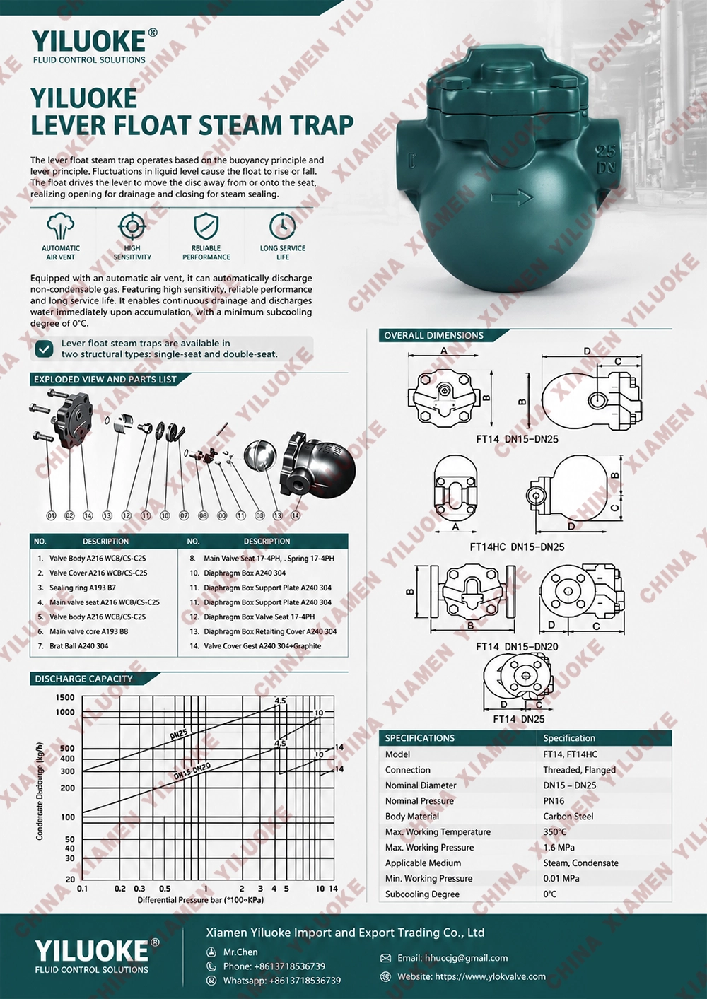


Lever Float Steam Trap


The lever float steam trap operates based on the density difference between steam and condensate. The change of condensate liquid level raises or lowers the float to drive the valve disc to open or close, so as to block steam and discharge condensate. It provides continuous condensate discharge and guarantees heat transfer, and works efficiently under heavy or light condensate load. It is commonly installed on low and medium pressure heat exchange equipment and pipelines in chemical plants, suitable for working conditions requiring no liquid accumulation, large discharge capacity and automatic temperature-controlled drainage devices.
Working Principle
When the equipment just starts up, the whole trap is at ambient temperature. The temperature sensing element inside the built-in diaphragm capsule contracts, so the valve opening is open to continuously vent initial air inside the pipeline for startup. When condensate flows into the trap from the inlet, air is discharged through the vent. The linked lever float rises with the condensate level, and the valve seat allows internal condensate to flow out from the drain outlet. When steam and hot condensate enter the trap, the temperature sensing liquid inside the diaphragm capsule expands under heat to drive the valve plate and close the vent. The linked lever float adjusts the opening of the drain outlet according to the condensate level to drain hot condensate. When condensate stops entering the trap, the lever float drops with the liquid level and closes the drain outlet. Since the drain outlet is always below the condensate surface, a water seal is formed to prevent steam leakage.
Connection Types
| DN15-DN25 Thread | BSP or NPT |
| DN15-DN25 Flange | EN 1092 PN16/PN25, ANSI 150 |
Main Parts Material
| Part | Material |
|---|---|
| Valve Body, Bonnet | A216 WCB |
| Bonnet Bolt | A193 B7 |
| Bonnet Gasket | Graphite + SS304/316 |
| Valve Seat | A276 430 |
| Float and Strainer | A240 304 |
| Air Vent Device | A240 304 |
Note: Trap material and surface paint can be customized according to customer requirements and actual operating environment.
Design Standards
| Design Standard | ISO6552, EN26704 |
| Face-to-Face Length | EN26554 |
| Test & Inspection | EN26948 |
Overall Dimensions
| Size | A | B | C | D |
|---|---|---|---|---|
| DN15 | 121 | 107 | 67 | 147 |
| DN20 | 121 | 107 | 67 | 147 |
| DN25 | 145 | 107 | 67 | 166 |
FT14HC Threaded Lever Float Steam Trap Dimensions
| Size | A | B | C | D |
|---|---|---|---|---|
| DN15 | 121 | 120 | 75 | 198 |
| DN20 | 121 | 120 | 75 | 198 |
| DN25 | 121 | 120 | 75 | 198 |
FT44 Flanged Lever Float Steam Trap Dimensions
| Size | A | B | C | D |
|---|---|---|---|---|
| DN15 | 150 | 107 | 101 | 55 |
| DN20 | 150 | 107 | 101 | 55 |
| DN25 | 160 | 70 | 70 | 100 |
Installation Instructions
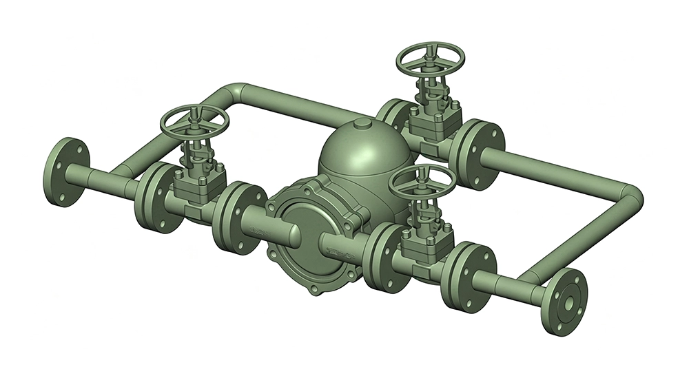
1. A bypass branch shall be preset on the pipeline during design, and isolating valves such as globe valves shall be installed before and after the trap to facilitate maintenance without shutdown.
2. Reserve about 100mm clearance around the trap during installation, and remove obstacles above the bonnet for future maintenance.
3. Isolate the trap in advance before pipeline purging.
4. In case of steam leakage or no drainage failure, please contact our after-sales service for timely troubleshooting.